To change the position of the edges, use the command Change the position of faces  .
.
•Toolbar area: Solid Modelling — Direct Modelling — Change the position of faces
•Main menu: Modelling — Faces — Change the position of faces
•Find and run the command using search field in Main menu bar |
Procedure
1.In the graphics area, select one or more faces of the solid whose position you want to change.

|
The faces being changed must belong to the same body.
|
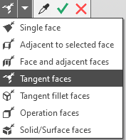
With a single selection, you can choose a face or a group of faces that meet a specific condition. To specify the condition, use the elements in the Quick Access Toolbar.
The selected faces are highlighted, and their names are displayed in the Faces field on the Options Panel.
2.In the Method group on the Parameter panel, select the method for changing the position of the faces. The set of operation parameters depends on the selected method. After setting the parameters, a phantom of the modified body appears in the graphic area. The absence of a phantom indicates that the operation cannot be performed.
•To distance  — displacement of edges in a given direction by a certain distance.
•Click in the Guiding object field. Specify the object in the graphic area or in the Design tree. The name of the object will appear in the Guiding object field.
The guiding object can be:
•straight-line object — sets the direction parallel to itself,
•flat object — sets the direction perpendicular to its plane,
•surface of revolution (except a sphere) - specifies a direction parallel to its axis.
You can also set the offset direction using a vector. To construct a vector, click the button Design vector  to the right from field Guiding object. The subprocess of vector design will start. Perform the steps required to build and click the button Create object. The system will return to the process of changing the position of the edges, the created vector will be automatically selected as a guiding object. to the right from field Guiding object. The subprocess of vector design will start. Perform the steps required to build and click the button Create object. The system will return to the process of changing the position of the edges, the created vector will be automatically selected as a guiding object.
•Specify the offset value of the edges in the field Distance.
You can reverse the offset direction by clicking the button Change the direction  to the right of the field Distance. to the right of the field Distance.
|
•Moving by points  — offset of the faces is determined by a vector built between two points. The direction of the vector is from the starting point to the ending point. The offset distance is equal to the length of the segment connecting the points.
•Click Starting point. Specify the first pointed object in graphic area or in Design tree. The name of the object will be displayed in the field Starting point.
•Specify the second point object in the graphic area or in the Design tree. The name of the object will be displayed in the field Ending point.
If you want to plot a point, click the button Build a point  to the right of the field Starting point/Ending point. The subprocess will start of building a point. Perform the steps required to build and click the button Create object. The system will return to the process of changing the position of the edges, the created point will be automatically selected as a pointed object. to the right of the field Starting point/Ending point. The subprocess will start of building a point. Perform the steps required to build and click the button Create object. The system will return to the process of changing the position of the edges, the created point will be automatically selected as a pointed object.
|
•To angle  — rotation of faces around the selected axis at a given angle.
•Click in the Axis field. Specify the axis of rotation in the graphic area or in the Design tree. The name of the object will be displayed in the Axis field.
In the Axis field, you can specify:
•straight-line object,
•surface of revolution (except sphere) - its axis will be selected.
If you want to build an axis, click the Design axis button  to the right of the Axis field. The axis building axis design subprocess will start. Perform the steps required to build and click the button Create object. The system will return to the process of changing the position of the faces, the created axis will be automatically selected as the axis of rotation. to the right of the Axis field. The axis building axis design subprocess will start. Perform the steps required to build and click the button Create object. The system will return to the process of changing the position of the faces, the created axis will be automatically selected as the axis of rotation.
•Specify the angle of rotation of the faces in the field Angle. You can also select its value from the drop-down list in this field. Negative values are possible.
You can change the direction of rotation of the faces relative to the rotation axis by clicking the Change direction button to the right of the Angle field.
|
•Moving by points  — rotation of faces around a selected axis by an angle specified by two points, the direction of rotation is from the starting point to the ending point.
•Click in the Axis field. Specify the axis of rotation in the graphic area or in the Design tree. The name of the object will be displayed in the Axis field.
In the Axis field, you can specify:
•straight-line object,
•surface of revolution (except sphere) - its axis will be selected.
If you want to build an axis, click the Design axis button to the right of the Axis field.The axis building axis design subprocess will start. Perform the steps required to build and click the button Create object. The system will return to the process of changing the position of the faces, the created axis will be automatically selected as the axis of rotation.
•Specify the first pointed object in the graphic area or in the Design tree. The name of the object will be displayed in the field Starting point.
•Specify the first pointed object. The name of the object will be displayed in the field End point.
If you want to plot a point, click the button Build a point to the right of the field Starting point/End point. A subprocess will start to construct a poin will start. Perform the necessary steps to construct the point, and click the Create Object button. The system will return to the face repositioning process, and the created point will be automatically selected as a point object.
|
3.If you want to rebuild the fillets on the boundaries of the selected faces as if they were built after changing their position, enable the Adapt fillets option.
4.If necessary, change the operation name in the Properties section of the Parameter panel.
5.To complete the operation, click the button Create object  .
.
The specified faces will change their position in the model, and a corresponding icon will appear in the Design tree. .
6.To complete the command, click the button Finish  .
.
Tips
•The values of the operation parameters can be set in the graphic area - using defining points.
•To set linear and angular parameters, you can use the commands geometrical calculator.
•You can assign tolerances to the values of operation parameters expressed in linear or angular quantities. To do this, call the Tolerance command located in the menu of the required parameter, or click the icon displayed in the parameter field (the icon is displayed if a tolerance is assigned to the parameter value).
•You can assign tolerances to operation parameter values expressed in linear or angular units. To do this, select the Tolerance command from the menu of the desired parameter, or click the icon displayed in the parameter field (the icon appears if a tolerance has been assigned to the parameter value).