|
Setting the trajectory for placing the sketch |
Scroll |
The trajectory on which the plane for sketch building is located is indicated in in the sketch placement process for On trajectory  method.
Step-by-step instructions
1.In the graphics area or in the Model Design Tree, select the objects that make up the trajectory:
•a 3D curve,
•line in the sketch,
•a sketch (specified in the Model Design Tree; if the sketch consists of several...) contours, then the first of them is selected as the trajectory),
•edge,
•a chain of above mentioned objects in any combination.
A line in a sketch, an edge, or a segment of a multi-segment curve is specified in the graphics area, while a sketch is specified in the Design Tree. A spatial curve can be specified in either the graphics area or the Design Tree.
By selecting a curve (sketch line) or edge in the graphics area, you can select a single object or a group of objects that meet a specific condition. To specify the condition, use the elements in the Quick Access Toolbar.
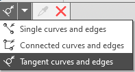
Selecting curves and edges based on conditions
If the objects that make up the path intersect or touch other curves (or edges, or sketch lines), you can select them entirely or in parts, divided by the intersection/touch points. This depends on the state of the Select parts of curves  button on the Quick Access Toolbar. More...
|
Trajectory objects can be indicated before invoking the command. In this case, during the placement of the sketch, the method On the trajectory |

|
When creating a sketch during construction Element by path or Surfaces by path In this regard, note the following features. •If a sketch is created before specifying the trajectory of the element/surface, then the trajectory indicated during the sketch placement process is transferred to the element/surface. •If the trajectory of an element/surface is defined before the creation of the sketch, it is transferred to the sketch placement process, and method On trajectory |
After specifying trajectory objects in the graphic area, a phantom of the sketch plane appears. It passes through the initial point of the trajectory, which is determined by the system in accordance with the direction of construction of trajectory objects, and is located perpendicular to it. A sketch coordinate system is displayed using Placement element  .
.
2.Specify the position of the point on the trajectory, through which the sketch plane must pass. The following methods are available.
•Specifying the offset of the point relative to the beginning of the trajectory.
Select a method to specify the offset using the button group Offset and enter the offset value.
 In % of the curve length — the value in % is entered in the field % of the curve length.
 By segment length — the value in mm is entered in the field Length.
 By the central angle of the arc (for a trajectory with the shape of an arc or a circle) - the value in degrees is entered in the field Angle or selected from the drop-down list in this field.
If it is required to set the offset value not from the beginning of the trajectory, but from its end, click the Change Direction button  .
.
|
You can set linear and angular parameters using the geometrical calculator. |
•Specify the snap point.
Activate the field Snap Point and specify a point constructed in the model. If the point lies on the specified trajectory, then the sketch plane will move to this point, and if not, to the point on the trajectory where the distance to the specified point will be minimal.
If the required point does not exist in the model, you can build it without interrupting the command. To do this, click Draw point  to the right of the field Snap Point and perform the necessary actions in subprocess of plotting a point. The created point will be automatically selected as the snap point. It is a separate object and can be edited in the normal way.
See Also
