|
Building a surface by path |
Scroll |
To plot a surface by path, use the Surface by path  command.

The parameters of the surface by path are configured in the same way as the parameters of the By path element.
|
The object defining the section or the path of its movement can be selected before invoking the command. If the specified object is suitable for defining a section, it automatically becomes the surface section along the trajectory. If the object cannot be used as a section but can define the path of its movement, then it is selected as the path. If the object can neither be a section nor a trajectory, the selection is reset. An area in the sketch is specified only during the execution of the command. |

Step-by-step instructions
1.Specify one of the following objects as the section:
• Sketch, closed area in the sketch,

•A flat curve, whether closed or open, including those consisting of multiple segments (the use of curves with child curve objects has specific characteristics)
•Edge of a flat face
•Flat face
Features of specifying objects of different types
The name of the object selected as the section is displayed in the Section field in the Main section of the Parameter Panel (if an area is selected in the sketch, the word Area is added to the text in the field).
2.Specify the path of the section. To do this, select one or more connected objects.
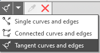

The names of the selected objects are displayed in the Path field.
More about setting a trajectory...
3.Use the Section movement button group in the Main section of the Parameter Panel to select the type of section movement along the path. The following options are available:
 Keep slope angle,
 Parallel to itself,
 Orthogonal to path.
Learn more about selecting the cross-section movement type...
All parameter values are displayed in the graphics area as a surface phantom.
4.You can add faces to the surface corresponding to the initial and final positions of the section. To do this, enable the Close Surface option. This option is available if a closed object is used as the section—a region in a sketch, a face, a closed contour, etc.
5.If the cross-section is a sketch, you can construct a surface whose cross-section shape changes as the cross-section moves along the path. To do this, in the Cross-Section Shape Change section, set the switch Changing shape Set it to Position I (On) and specify the cross-section variation parameters (for example, functions that vary the dimensions along the path, or the desired values of the variables at selected points along the path). In addition, the cross-section shape is influenced by parametric constraints between sketch elements and model objects. A
sketch can contain either a closed or an open contour. The cross-section shape variation parameters are specified in the same way as for a path element (see the Cross-Section Shape Variation Parameters section).
4.If the cross-section shape changes as it moves along the path, you can see what the cross-section looks like at various points along the path. To do this, in the section Cross-section check Set the Display sections switch to the I (On) position and configure the section display. Learn more about checking the section shape...
4.If necessary, change the construction optimization option (this option is available if the cross-sectional shape remains constant along the entire length of the path). This may change the appearance of the surface along the path if the path has a complex shape (for example, a spiral with a variable pitch). Expand the sectionA dvanced options and select the option you want from the list Optimization Version. For a simple trajectory, all optimization options produce the same result.
4.If necessary, specify the name of the surface along the path and its display properties using the controls located in the Properties section of the Parameter Panel. Controlling the color and optical properties of objects...
5. To complete the operation, click the Create Object button.
A surface along the path appears in the graphics area, and its icon appears in the Construction Tree.
|
If the construction results in multiple surfaces rather than a single one (for example, when specifying a curve with multiple contours as the cross-section), the process of modifying the set of surfaces begins after the operation is completed. Select the surfaces to keep. Learn more... Each of the retained surfaces is a separate object. You can, for example, change the surface color, hide it, or move it to a layer. However, they were all created by a single operation, so editing the operation will affect all of these surfaces. |
10. To complete the command, click the Finish button.
|
When editing the Surface by path operation, the Parameter Panel contains a Creation options section with a Create with matching button Use this button if the source section objects are replaced by other objects. This will preserve the associative relationship between the geometry resulting from this operation and its reference objects. Learn more about setting associations... |
 .
.See also
