|
Building planes |
Scroll |
In KOMPAS-3D you can construct:
•plane at an angle to another plane,
•plane through edge and point,
•plane though point parallel to another plane,
•plane through point perpendicular to edge,
•plane tangent to face at point,
•plane through edge parallel/perpendicular to another edge,
•plane through edge parallel/perpendicular to face,
|
Plane creation commands are grouped together. While executing a group command, you can switch to execution of another one using buttons of the Parameter Toolbar header. If an object to be built is already selected in the current command, it remains selected when you switch to another command (if an object of the same type is required for building). |

An auxiliary plane located at a specified distance from the specified flat object is built using the Offset Plane  . command. This command also enables building multiple offset planes in a single run.

Step-by-step instructions
1.Specify a flat object, relative to which the offset of the new plane is specified. The name of the selected object is displayed in the Base Plane field on the Parameters toolbar.
The phantom of the plane being created will appear in the graphics area.
2.In Distance field enter the distance from the flat object to the plane to be created.
3.Set the direction of the shift using the Change direction button to the right of the Distance field. After pressing the button, the arrow on the icon will change to the opposite.
4.If required, you can simultaneously build several planes which will be offset relative to each other at the specified distance. To do this, enter the number of planes in the Number. Phantoms of planes will appear in the graphic area.
|
Note that if multiple offset planes are created simultaneously, each of them will be displayed in the Model Tree as a separate object. You can edit each plane separately, independently from the others. |
5.If necessary, change the direction of the plane's normal by clicking the Normal Direction  button. The arrow indicating the direction of the normal in the graphical area will point in the opposite direction. Learn more...
6.To finish creating the object, click the Create Object  button.
7.To finish the task, click the Finish button.
|
|
a) |
b) |
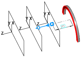
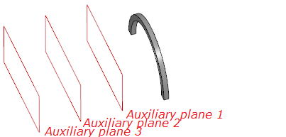
Example of building multiple offset planes
a) setting a base plane and a distance, b) operation result
Additional features when building...
A construction plane passing through the selected three point objects is built using the Plane through three points option.
Procedure
1.Specify three point objects. Their names will appear in the Point 1, Point 2, and Point 3 fields on the Parameter Panel.
A phantom of the plane being created will appear in the graphics area.
Point objects are specified in the graphics area or in the Design Tree. If necessary, you can construct a point while the command is running. To do this, click the Build Point button  to the right of the field Point 1 (Point 2, Point 3) on the Parameter Panel. The the point design subprocess.
2.If necessary, change the direction of the plane's normal by clicking the Normal Direction button. The arrow indicating the direction of the normal in the graphical area will point in the opposite direction. Learn more...
3.To finish creating the object, click the Create Object button.
4.To finish the team's work, click the Finish .
Additional features when building...
A plane at an angle to another plane
A construction plane passing through a straight-line object at the specified angle to a flat object is built using the Plane at Angle  command. This command also enables building multiple planes at the specified angle to each other and passing through the same straight-line object in a single run.
Step-by-step instructions
1.Select a flat object at an angle to which the plane should be drawn. Its name will appear in the Base Plane field on the Parameter Panel.
2.Select a linear object through which the plane should pass. Its name will appear in the Axis field, and a phantom of the plane being created will appear in the graphics area.
|
The straight-line object must be parallel to the flat object or belong to it. |
If the desired straight-line object is not in the model, build the axis by pressing the Build the axis  to the right of the field Axis. The the axis construction subprocess.
2.Set the angle between the flat object and the plane to be created in the Angle field, or select a value from the drop-down list.
4.Specify the direction to which the indicated angle should be put aside from the flat object, using Change Direction button to the right of the Angle field. After pressing the button, the arrow on the icon will change to the opposite.
3.If required, you can simultaneously build multiple planes located at the specified angle to each other and passing through the selected straight-line object. To do this, enter the number of planes in the Number. Phantoms of planes will appear in the graphic area.
|
Note that if multiple planes are created simultaneously at a set angle, each of them will be displayed in the Model Tree as a separate object. You can edit each plane separately, independently from the others. |
6.If necessary, change the direction of the plane's normal by clicking the Normal Direction button. The arrow indicating the direction of the normal in the graphic area will point in the opposite direction. Learn more...
7.To finish building the plane, click the Create object button .
8.To complete operation of the command, click Finish .
|
|
a) |
b) |
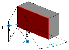
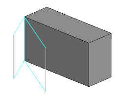
Example of building multiple planes at a set angle
a) setting a base plane and an angle, b) operation result
Additional features when building...
A construction plane normal to the revolution surface (except for a sphere) is built using the Normal Plane  .
.
Step-by-step instructions
1.Specify the rotation surface. Its name will appear in the Revolution Surface field on the Parameter Panel.
A phantom of the plane being created will appear in the graphics area. By default, the plane passes through the axis of the surface of revolution and the point of this surface with zero values parameters U and V.
2.If necessary, specify the position of the plane relative to the existing flat object. To do this, specify a flat object parallel to the axis of rotation. The name of the selected object will appear in the Base Plane field on the Parameter Panel.
The position of the phantom will change: the plane will pass through the axis of the surface of rotation parallel to the specified object.
3.Set the rotation angle of the plane in the field Angle or select a value from the drop-down list. The rotation angle is measured from the current position of the plane.
4.Specify the angle measurement direction using the Change Direction button located to the right of the Angle field. After pressing the button, the arrow on the icon will change to the opposite.
5.If necessary, change the direction of the plane's normal by clicking the Normal Direction button. The arrow indicating the direction of the normal in the graphic area will point in the opposite direction. Learn more...
6.To finish building the plane, click the Create object button.
1.To complete operation of the command, click the Finish button.
Additional features when building...
A construction plane tangent to the cylindrical or conical face of the model is built using the Tangent Plane  command.
Step-by-step instructions
1.Specify a cylindrical / conical face and a flat object passing through the axis of this face. The name of the selected object will appear in the fields Revolution Surface and Base plane on the Parameter Panel.
A phantom of the plane being created appears in the graphics area: it passes through the line of intersection between the cylindrical / conical face and the flat object perpendicular to the latter.
1.Specify which side of the cylindrical / conical face the tangent plane should be constructed. To do this, set the toggle switch to the desired position Position 1/Position 2.
2.Set the rotation angle of the plane in the field Angle or select a value from the drop-down list. The rotation angle is measured from the current position of the plane.
3.If necessary, change the direction of the plane's normal by clicking the Normal Direction button . The arrow indicating the direction of the normal in the graphical area will point in the opposite direction. Learn more...
4.To finish building the plane, click the Create object .
5.To complete operation of the command, click Finish .
Additional features when building...
A construction plane passing through the selected straight-line and point objects is built using the Plane through edge and point  .
.
Procedure
1.Select the point object through which the plane should pass. Its name will appear in the Point field on the Parameter Panel.
If the object you need isn't in the model, create it by clicking the Create Point button to the right of the field Point. The point construction subprocess will start.
2.Select a linear object. Its name will appear in the Edge field on the Parameter Panel.
If the desired object is not in the model, create it by clicking the Create Axis button to the right of the field Edge. The axis construction subprocess will start.
After specifying the objects in the graphics area, a phantom of the plane being created appears.
3.If necessary, change the direction of the plane's normal by clicking the Normal Direction button. The arrow indicating the direction of the normal in the graphical area will point in the opposite direction. Learn more...
4.To finish constructing the plane, click the Create Object button.
5.To complete operation of the command, click the Finish .
Additional features when building...
A construction plane passing through the specified flat curve is built using the Plane through plane curve  command..
Step-by-step instructions
1.Specify the curve through which the new plane should pass. Its name will appear in the Curve field on the Options Panel.
The following can be used as a curve:
•a sketch line,
•a spline (or polyline) with three vertices,
•an arc,
•a conic curve,
•other plane curves: an edge shaped like a circle, an ellipse, etc.
After specifying the curve, a phantom of the plane being created will appear in the graphics area.
2.If necessary, change the direction of the plane's normal by clicking the Normal Direction button. The arrow indicating the direction of the normal in the graphical area will point in the opposite direction. Learn more...
3.To finish constructing the plane, click the Create Object button.
4.To complete operation of the command, click Finish .
Additional features when building...
Plane through Point Parallel to Another Plane
A construction plane passing through the point object parallel to the plane object is built using the Plane through point parallel to another plane  .
.
Step-by-step instructions
1.Select a flat object parallel to which the plane should be drawn. Its name will appear in the Base Plane field on the Parameters Panel.
2.Select the point object through which the plane should pass. Its name will appear in the Point field on the Parameter Panel.
If the desired object is not in the model, create it by clicking the Create Point button to the right of the field Point. A the subprocess for constructing a point wll start.
After specifying the objects in the graphics area, a phantom of the plane being created appears.
3.If necessary, change the direction of the plane's normal by clicking the Normal Direction button. The arrow indicating the direction of the normal in the graphical area will point in the opposite direction. Learn more...
4.To finish constructing the plane, click the Create Object button.
5.To finish the plane construction command, click the Finish button.
Additional features when building...
Plane through Point Perpendicular to Edge
A construction plane passing through a point object perpendicular to the curve (edge, sketch line, spline, etc.) is built using the Plane through point perpendicular to edge  .
.
Step-by-step instructions
1.Specify the curve through which the plane should pass. Its name will appear in the Edge field on the Parameter Panel.
If the desired object is not in the model, create it by clicking the Create Vector  button to the right of the field Edge on the Parameters Panel. This will start the vector construction subprocess.
2.Specify the point object through which the plane should pass. The object may or may not belong to the specified curve.
The name of the selected object will appear in the Point field on the Parameter Panel.
If the desired object is not in the model, create it by clicking the Create Point button to the right of the field Point. A the subprocess for constructing a point will start.
After specifying the objects in the graphics area, a phantom of the plane being created appears.
3.If necessary, change the direction of the plane's normal by clicking the Normal Direction button. The arrow indicating the direction of the normal in the graphical area will point in the opposite direction. Learn more...
4.To finish constructing the plane, click the Create Object button.
5.To complete operation of the command, click Finish .
Additional features when building...
The plane tangent to a face at a point
A construction plane tangent to the selected face at the set point is built using the The plane tangent to a face at a point  .
.
Step-by-step instructions
1.Specify the face to which the plane should go. The name of the selected object will appear in the field Surface on the Parameter Panel.
The selected face will display a phantom of its theoretical surface The phantom of the new plane is displayed as a rectangle, and the grid of isoparametric curves U and V. By default, the plane passes through the point of specifying the face.
1.Set the position of the tangent plane. To do this, specify the position of the point through which the plane will pass, in one of the ways:
•Set the offset points along the isoparametric curves U and V. Values for the U and V parameters are entered into the field UV parameters, % on the Parameters panel.
•specify the point object with which the tangent plane will be associated. Thanks to this connection, the plane will follow the object when its position changes.
The name of the selected object appears in the field Snap point.
|
To specify the position of the plane, point objects can be specified as belonging to the selected face, as well as not belonging to it, but projecting onto this face. The position of the created plane in this case is determined by the projection. |
If the desired point object is not in the model, build a point by clicking the Build Point button to the right of the field Snap Point on the Parameters Panel. The the point building subprocess will start.
3.If necessary, change the direction of the plane's normal by clicking the Normal Direction button. The arrow indicating the direction of the normal in the graphical area will point in the opposite direction. Learn more...
4.To finish building the plane, click the Create object button.
5.To complete operation of the command, click Finish .
Additional features when building...
Plane through Edge
Parallel/Perpendicular to Other Edge
A construction plane passing through the specified straight-line object parallel or perpendicular to another straight-line object is built using the Plane through edge parallel/perpendicular to another edge  command.
Step-by-step instructions
1.Specify the straight-line object through which the plane should pass. Its name will appear in the Object 1 field on the Parameters toolbar.
2.Select position of the plane – parallel or perpendicular to another rectangular object. To do this, press the relevant button in the Plane position group.
 Parallel to edge
 Perpendicular to edge
3.Specify a linear object parallel (or perpendicular) to which the plane should be drawn. Its name will appear in the Object 2 field on the Parameter Panel.
A phantom of the plane being created will appear in the graphics area.
4.If necessary, you can specify the first selected object as the edge parallel or perpendicular to which the new plane will pass. To do this, click Swap  to the right of the Object 1 field until you select the second object. After clicking the button, the name of the selected object will appear in the field Object 2, and the field Object 1 will be cleared.
5.If necessary, change the direction of the plane's normal by clicking the Normal Direction button. The arrow indicating the direction of the normal in the graphical area will point in the opposite direction. Learn more...
6.To finish constructing the plane, click the Create Object button.
7.To complete operation of the command, click Finish .
Additional features when building...
Plane through Edge
Parallel/Perpendicular to Face
A construction plane passing through the selected straight-line object parallel or perpendicular to another flat object is built using the Plane through Edge Parallel/Perpendicular to Face  .
.
Procedure
1.Select a linear object through which the plane should pass. Its name will appear in the Edge field on the Parameters panel.
2.Select the plane position — parallel or perpendicular to another flat object. To do this, press the relevant button in the Plane position group.
 Parallel to face
 Perpendicular to face
3.Select a flat object parallel (or perpendicular) to which the plane should be created. Its name will appear in the Face field on the Parameter Panel.
A phantom of the plane being created will appear in the graphics area.
4.If necessary, change the direction of the plane's normal by clicking the Normal Direction button. The arrow indicating the direction of the normal in the graphic area will point in the opposite direction. Learn more...
5.To finish constructing the plane, click the Create Object button.
6.To complete operation of the command, click Finish .
Additional features when building...
A bisector plane of a dihedral angle is built using the Median Plane  command.
Dihedral angle – part of the space bounded by two half-planes, the boundary of each of which is their common straight line. These half-planes are called faces of the dihedral angle, and the straight line – edge of the dihedral angle. The angle between the lines of suppression of the faces of a dihedral angle with a plane perpendicular to the edge of the dihedral angle is called linear angle of the dihedral angle.
Bisecting plane of the dihedral angle is the plane passing through the bisector of the linear angle and the edge of this dihedral angle.
The dihedral angle for constructing the middle plane can be specified:
•faces – for this you need to specify two flat objects,
•linear angle – for this you need to specify two straight line objects,
•the face and side of the linear angle – for this you need to specify flat and rectilinear objects.
|
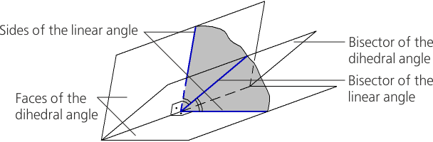
Dihedral angle and its bisector plane
Step-by-step instructions
1.Specify the sides of the dihedral angle to construct the median plane. The names of the selected objects will appear in the Object 1 and Object 2 fields on the Parameter Panel.
A phantom of the plane being created will appear in the graphics area.
2.If necessary, use the Position 1/Position 2 switch to adjust the position of the plane you are creating relative to the specified objects. The following construction options are available:
•Step 1 — Construct the bisector plane,
•Situation 2 — Construct a plane perpendicular to the bisector and passing through the edge of the dihedral angle.
If the specified objects are parallel, the construction is performed as follows.
•If the objects are planar, then regardless of the position of the switch, the median plane is constructed parallel to them at an equal distance from them.
•If the objects are straight lines, the median plane is constructed perpendicular to the plane passing through them and, in the first position, at an equal distance from them, and in the second position, such that the objects intersect the resulting plane.
3.If necessary, change the direction of the plane's normal by clicking the Normal Direction button. The arrow indicating the direction of the normal in the graphical area will point in the opposite direction. Learn more...
4.To finish constructing the plane, click the Create Object button.
5.To complete operation of the command, click the Finishbutton.
Additional features when building...
•The distance and angle values can be changed in the graphical area of the model – using defining points.
•You can use the Geometric Calculator commands to specify linear and angular parameters.
•You may assign tolerances, specified in linear or angular units, to operation parameter values. To do this, you should call the Tolerance command located in the menu of the required parameter, or click the  , displayed in the parameter field (the icon appears if a tolerance has been assigned to the parameter value). Learn more about assigning tolerances...
