|
Projection depth control |
Scroll |
In some cases, the associative drawing does not need to show all the objects of the model, but only a part of them. The objects whose images should be present in the view can be specified by limiting the projection depth, i.e. highlighting the projected area in the model. Using this technique allows you to give an idea of the device of the product with the necessary degree of detail.
The projected area is defined in the drawing by two parallel planes: the first coincides with the dimensional plane of the model closest to the observer, the second is located behind the first and is the boundary plane. The view will display only those objects that are located between the planes.
|
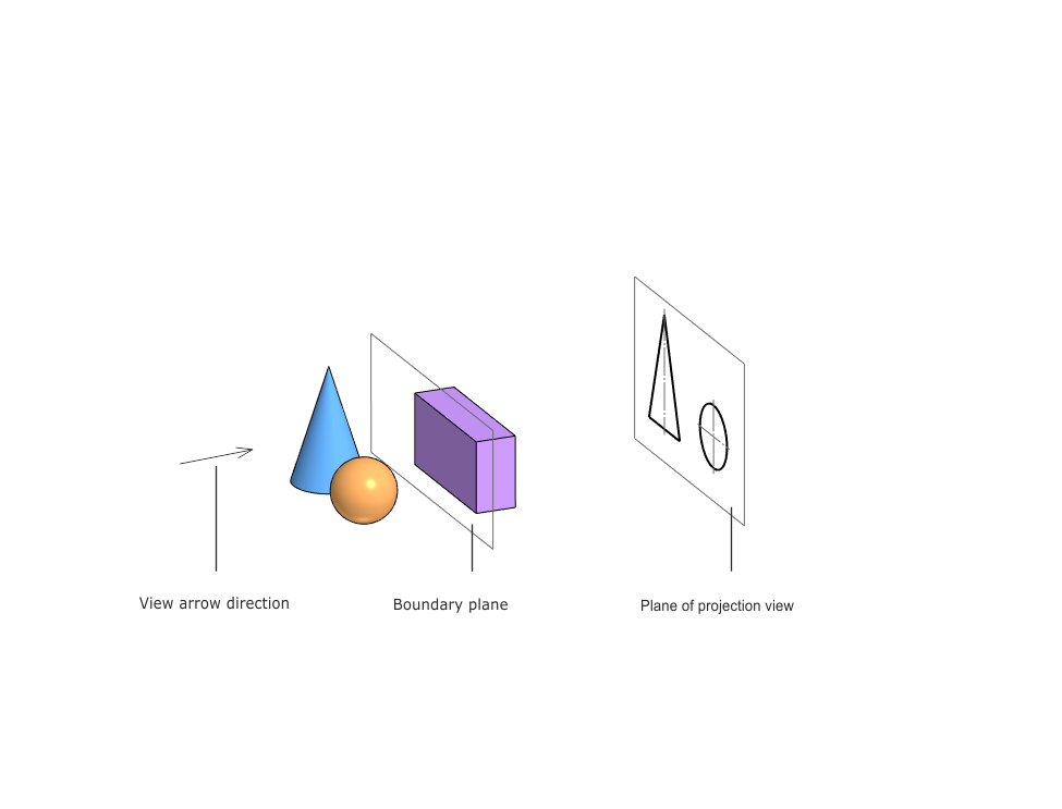
Limitation of projection depth
You can enable the projection depth limit and adjust it when creating an associative view or when editing an existing view. To do this, turn the Projection Depth switch on the View Parameters Panel to position I (on). After that, the Boundary plane controls will appear on the Parameters Panel.
|
The Projection Depth element is available for all associative views, except Standard, Enlarged detail, Broken-out section and Cut/section, if a Section is selected. |

There are two ways to set the boundary plane, which are determined by the position of the switch Distance/Boundary plane:
•If the Distance position is selected, then the boundary plane is located at a specified distance from the dimensional plane of the model closest to the observer. To set the distance, enter it in the Distance field manually or using a geometric calculator. By default, the distance is 10.
•If the Boundary Plane position is selected, the boundary plane is positioned relative to the origin and is set manually in the graphic area of the drawing. To do this, there must be another associative type in the drawing. The projection plane of the second view must be perpendicular to the projection plane of the view for which the projection depth is adjusted. When the cursor passes over the second view, a phantom trace of the boundary plane is displayed in the graphical area in the form of a straight line.
•After the Plane is specified, the text Plane is specified appears in the Boundary Plane field, and the field name becomes a link. Clicking on this link allows you to set the plane again. If you want to complete the process of setting the plane without changing it, click Stop Selection.  .
.
|
When using the Distance method, the position of the boundary plane depends on the dimensional plane of the model closest to the observer. If this plane is displaced as a result of model changes, then the position of the boundary plane is determined anew. When choosing the Boundary Plane method, the position is fixed relative to the origin and does not change when the model is rebuilt. |
|
When creating an associative view, the boundary plane can only be set using the Distance method, and during editing it can be set using any of the methods. |
If the boundary plane intersects the objects (components, bodies, surfaces) of the model, then you can select the option to display them on the view using a group of buttons. Component on boundary:
 Show up to the boundary — only the part of the object that falls into the space up to the boundary plane is displayed.;
 Show the whole thing — the object is displayed in full;
 Hide — the object is not displayed.
After you have completed the projection depth setting, set other view parameters (if necessary) and click  . If the setting was performed while editing an existing view, rebuild the drawing, by pressing the <F5> key. Model objects located outside the boundary plane will no longer be displayed on the view.
Views with limited projection depth are marked in the Drawing Tree with an icon  .
.
|
Changes in one of the views have no effect on the image in other drawing views. |
By default, the Drawing Tree displays a complete list of objects of the model projected into the view, even if not all objects are shown in the view. To display only the objects actually present in the view, call the command from the context menu of this type Show only visible in the tree.
Features of setting the projection depth in sections
If the associative view is a section, then when adjusting the projection depth using the Distance method, the dimensional plane closest to the observer coincides with the secant plane of the section. In the case of a stepped section, with the secant plane closest to the observer.
In a polyline section, for each of its parts, the dimensional plane coincides with the secant. in other words, the boundary planes are constructed in parallel at a given distance from each secant plane of the section.
In the view with local sections, the boundary plane is defined from the dimensional plane closest to the observer.
See also
