|
Overview |
Scroll |
Multiline – a geometric object consisting of one or several lines, built equidistantly to the baseline.
Multiline can be used to depict pipelines, walls, partitions, fences and other extended objects with a contour of several lines.
|
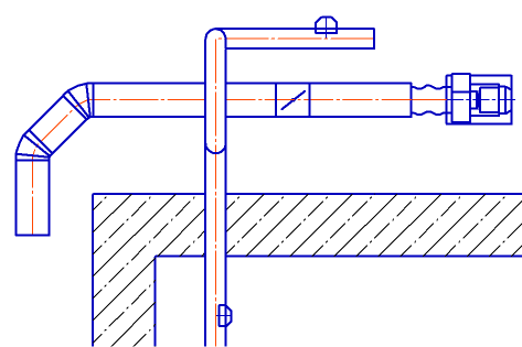
Example of using multilines
|
It is not recommended to depict several objects as one multiline (for example, a group of parallel pipelines). |

The baseline of a multiline consists of segments: line segments, arcs, splines, etc. You can add existing objects to the baseline. The desired type of object (segment, arc, or adding an existing object) is selected in the process of building a segment.
In the process of building, you can change the baseline configuration by adding, deleting or moving its vertices. There is a choice of a way to bypass the angle at each vertex of the baseline – a way to connect the lines of a multiline at the junction of segments.
Lines in a multiline may have different styles. The maximum number of lines is 64. Line parameters are set during construction. The default values of the multiline parameters can be changed in the dialog Multiline.
All lines of a multiline are located in one layer.
User parameters of a multiline can be saved for later use by writing to a file template. Using templates, you can create single-type multi-lines.
Multilines are selected, edited and deleted entirely. As a result of editing, line sections can be deleted. To restore deleted parts of a multiline, use the commands Restore deleted section of multiline and Restore multiline integrity.
Multiline may be part of macro-element and group.
See Also