|
Conditions for generation of projection designations in views |
Scroll |
The conditions described in this section apply to transfer of all dimensions, captions, tables and designations, except for centerlines, to a view. To learn about transferring centerlines, see section Centerlines transferred from the model.
If the Configuring view parameters Included is the transfer of dimensions, captions, tables and designations (these actions are described in section Objects and Detailing elements), corresponding projection designations are generated in the view if the following conditions are met.
•The plane of projections of a view is parallel to the plane for setting the dimension, caption, table or designation.
•In a view, objects (components, solids, surfaces, lines) to which dimensions or designations are set are displayed. For example, reference numbers will be shown in a view if faces or sections of faces from which positional leaders depart are visible.
•Table names are transmitted in the event that their display is turned on in the model. Editing table names in the drawing is not available.
|
Dimensions, captions, tables and designations excluded from calculation in model are not transferred into drawing. |

To generate projection designations in sections, cuts, detail views, and leader elements, additional conditions must be met.
•In the section, only those dimensions, captions, tables, and designations are transferred whose plane of setting coincides with the plane of the section.
•Transfer of a dimension, caption or designation to a cut, leader element or detail view depends on the position of points which are regarded as snap points (see table Snap points of dimensions and designations).
•Dimensions, captions, tables and designations are transferred into a cut if none of their snap points is cut by the section line.
•Dimensions, captions, tables, and designations are transferred into an leader element or detail view if projections of all their snap points are inside the contour that limits the view.
|
The passed dimensions, designations and captions may be automatically hidden, for example, if a new projection designation is a duplicate of another existing one. You can enable display of hidden projection designations using the View – Show Hidden Designations command. More details on managing display of projection designations... |
Note that the projection designations matching the linear and angular dimensions are generated in the associative view and in case if projections of their snap points are closed by lines of the visible boundary, for example, as shown in the figure.
|
|
a) |
b) |
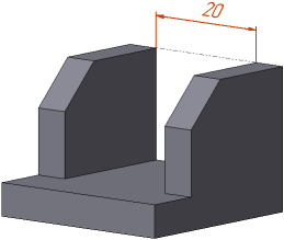
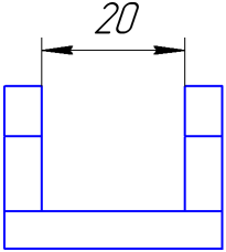
Linear dimension in the model (a) and its matching projective dimension in the associative view (b)
Snap points of dimensions and designations
Object |
Snap Points |
|
linear, linear from line to point, angular dimensions |
start points of extension lines |
|
radial, diametric dimensions |
center of measured circle or arc |
|
leader line, reference numbers, markings, stampings, surface finish on landing, bases, geometric and positional tolerances |
end points of branchings |
|
designation of surface finish without landing |
point of symbol setting |
|
caption |
snap point |
|
table |
snap point |