|
Outline |
Scroll |
You can plot face outline – a line that separates the visible part of a surface from the invisible part. In the points of the face outline, the normal of the face is perpendicular to the gaze direction.
Edges of the face are not included in the outline.
|
An outline cannot be plotted if the face is flat or the normal of the face in every point is perpendicular to the gaze direction. |

You can plot an outline for one face or for a set of faces, see the figure.
|
|
a) |
b) |
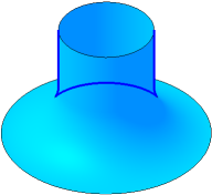
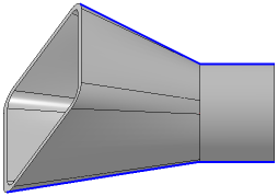
Outline: a) of a single face; b) of a set of faces
To plot an outline, use the Outline Line  .
.

Step-by-step instructions
1.Select the face or set of faces in the graphic area. You can select a solid or a surface in the Design Tree if you need to plot an outline for all the faces of a solid or surface. The name of the selected object is displayed in the Surface field on the Parameter Panel. A phantom of the outline will be displayed In the graphic area. By default, the outline is plotted along the gaze direction, perpendicular to the screen surface.
2.If you need to define other gaze direction, select the guiding object or create a vector. Details...
3.If you need to fix the outline in the shape corresponding to the current position of the model, enable the Fix Direction option. If this setting is disabled, the outline is rebuilt every time the model orientation is changed. An outline may consist of one or several segments – contours.
4.Select the outlines to plot if needed. Details...
5.You cat set the name, The color and Display parameters outline. To do that, use the Properties section.
6.To complete the operation, click Create an object  .
.
The outline will be displayed in the graphic area; the object with its icon in the Design Tree and subordinate objects corresponding to the number of separate contours in the curve.
7.To complete operation of the command, click Finish  button.
See Also
Notes on working with curves that have subordinate curve objects