|
Length of bend widening |
Scroll |
Bend extension is a part of the sheet element adjoined to the bend opposite to the edge along which this bend is located.
|
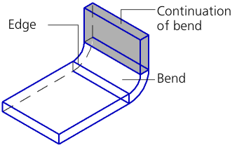
Bend and its extension
The bend extension parameters are set using the Bend Extension group of elements.
To select a method for plotting the bend extension, use the Tracing mode group of buttons. The following options are available:

Select a method and set the required parameters.
If you create a bend by one edge, the lengths of sides of the bend extension can be set separately. To do this, set the By Two Sides toggle switch to I (enabled). The second group of elements Bend Extension will appear on the Parameters bar. Follow the steps above for the second side of the extension.
The figure shows an example of how the bend extension is built with the same and different length of the sides.
|
|
a) |
b) |
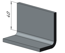
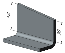
Example of forming the bend extension
a) By two sides in position 0 (disabled)
b) By two sides in position I (enabled)
 With specified length
The bend extension has a user-defined length.
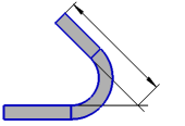
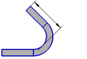
You can define the bend extension length in various ways. To select the desired method, use the group of buttons Setting of length group of buttons (see the table). The extension length is set in the Length field. The zero value in this field means absence of the bend extension.
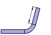
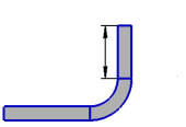
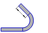
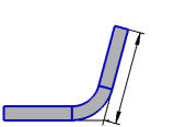
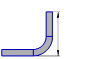
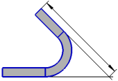
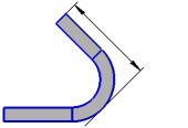
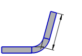
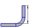
Schemes for setting the bend extension length
(the scheme shows the part projection onto the plane perpendicular to the edge along which a bend is built)
Method |
Bend angle from 0° to 90° |
Bend angle 90° |
Bend angle greater than 90° |
|
|
Bend Extension |
|
|
|
|
Along the outer contour line |
|
|
|
|
By tangency outside |
|
|
|
|
Along the inner contour line |
|
|
|
|
By tangency inside |
|
|
|


|
Setting the length using the Along the outer contour line and Along the inner contour line methods is available for angles from 0° to 180°. |

The bend extension length is automatically defined by the position of the selected object – a vertex or a flat face (plane).
To select an object, specify it in the graphics area or in the Design tree. The name of the selected object is displayed in the Object field.
When you select a vertex, the bend extension has such a length when its end face (or an edge of the end face adjacent to the extension side if the lengths of sides are set separately) is aligned with the plane that passes through the specified vertex perpendicular to the construction direction.
When you select a face, such a length of the bend extension is calculated at which its characteristic point belongs to the selected face or its extension (see Figure).
Defining points of the bend extension are displayed on the phantom. Their number depends on the By Two Sides switch position:
•when set to 0 (disabled) – one point in the middle of the edge of the end face;
•when set to I (enabled) – two points at the corners of the end face.
|
|
a) |
b) |
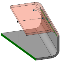
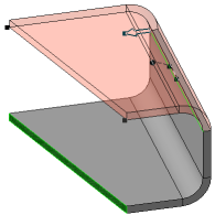
Building the bend extension up to the face
a) By two sides is disabled;
b) By two sides is enabled, the same face of the sheet solid
is specified as the border for both sides
If you want the end of the bend extension to "go over" the specified object or "not to reach" it, enter the required valued in the Move field. A zero value in this field means that the bend extension is created exactly up to the object.
The counting direction is set using the To Object/From Object  button to the right of the Move field.
Offset can be also set by dragging the respective defining points in the graphics area.
When you build the bend by multiple edges, extensions of all bends have the same length. It is defined by the position of the specified object from the first bend. The first is the edge which is built along the edge located in the first position in the Ribs field.
|
Bend construction using the To Object method is not possible for all angle and radius values. Disappearance of the bend phantom after entering a value for the angle and/or radius indicates that construction is impossible. |
