|
Controlling numerical parameters of objects |
Scroll |
Numerical parameter states
Numerical parameters which depend on points specified in the graphic area can be in one of three states: fixed, active, auxiliary. The parameter state is indicated by an icon to the left from the parameter value. Icons and descriptions of states are listed in the table.
Name |
Description |
|
|
Fixed |
The value of this parameters is accepted by the system. It remains unchanged when changing the rest of parameters and is displayed on the object phantom. |
|
Active |
The system expects the value of this parameter to be entered by specifying the point using the mouse in the graphic area. |
Auxiliary |
A construction parameter does not have an icon. The value of this parameter either is not set yet, or depends on the other parameter values (in this case it is fixed automatically after fixing the parameter it depends on). You can set and fix a construction parameter in any time. |

For example, the figure shows the Parameter Panel when constructing a polygon. The first point specified during construction defines the polygon center coordinates. The second point – a point on the circle – defines also the Diameter/radius and Rotation Angle parameters of the polygon. The Number of Vertices parameter is always entered manually, i. e. does not depend on specifying points, therefore it can have no state icon.
|
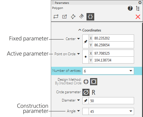
Polygon parameters: Center and Diameter of the inscribed circle are fixed,
Point on circle parameter is active, Angle — auxiliary.
Fixing and releasing numerical parameters
Fixing a parameter can be viewed as constraint of the number of possible configurations of the object being created/edited, and releasing a parameter, on the contrary, as increasing the number of configurations.
The fixed parameter value is not changed, and other – free – parameters remain available for changing. The sign that the parameter is fixed is an icon  to the left from the parameter value, and the absence of the icon indicates a free parameter. A free parameter can be active or construction.
Fixing the parameter value is done automatically or manually.
•Automatic fixing occurs if the parameter value has been set by specifying a point in the graphic area or obtained using geometrical calculator.
•Manual fixing is done by pressing the <Enter> key (after entering the value or expression).
Releasing (or unfixing) of the parameter is done only manually – to do this you should click on the Parameter Panel. After releasing the parameter becomes either active or construction.
Until fixing of an object being created/edited in the document you can fix and release its parameters any number of times.
Consider fixing and releasing parameters using an example of constructing and editing s line segment in the graphic document.
Example 1: Construction of a segment with a length of 100 mm.
Step-by-step instructions
1.Call the Segment command.
In the Parameter Panel, the Starting Point parameter is active, i. e. the system awaits specifying the first vertex of the segment. When moving the cursor, its current coordinates are displayed in the Starting Point field. The remaining parameters are construction, their fields are empty.
2.Specify the starting point of the segment in the graphic area.
The Starting Point parameter is automatically fixed, the End Point parameter becomes active. The Length and Angle parameters are construction. When moving the cursor, its current coordinates are displayed in the End Point field, and the Length and Angle fields display the length and the slope angle of the segment which correspond to the current cursor position. A phantom of the segment appears in the graphics area.
3.In the Length field, enter the number 100 and press <Enter>.
The Length parameter is fixed manually, the states of remaining parameters are not changed. Moving the cursor changes only the coordinates of its end point and the slope angle, and the length remains constant.
Now, until the ending vertex of the segment is specified, you can change any of the parameters which were set before: enter and fix the new coordinates of the starting point or the segment length. You can also refuse to fix the length by clicking to the left of the value of this parameter.
4.Click in an arbitrary point of the graphics area.
The End Point and Angle (as well as Length if it was released) parameters are fixed, and the segment itself is automatically fixed in the document.
To complete constructing the segment, you can also enter and fix its angle – the appropriate end point coordinates will be calculated and fixed automatically.
Example 2: Changing the length of a previously created segment while keeping the inclination angle.
Step-by-step instructions
1.Double–click on the segment.
The Parameter Panel displays the same parameters as when creating a segment. All of them are fixed.
2.Specify what point of the segments should be moved and how much. This depends on the source data.
•If the segment length is known, enter it in the Length field and press <Enter>. By default the ending vertex of the segment is shifted, i. e. the system calculates such coordinates of this point that the segment length is equal to the set one. If you need to move the starting vertex, before changing the length unfix the Starting Point parameter.
•If the new position of the segment vertex is set by specifying the point in the graphic area, unfix the Length and Starting Point parameters (or End Point – depending on what vertex needs to be moved). After that specify the point in the document. The new coordinate and length values appear in the appropriate fields and are fixed.
3.Click Create Object  in the header area of the Parameter Panel.