|
Texture |
Scroll |
If during manual configuration of the display parameters Object texturing available.
Procedure for setting a texture
In KOMPAS-3D, you can select a raster image that will be displayed on the faces of the model object. This enables displaying on the screen the most realistic image of a material the object is made of, to simulate the surface relief, etc.
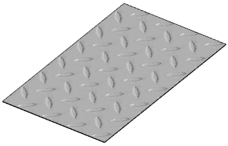
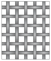
Using texture in models with knurling, perforation, corrugation, etc. allows to avoid creating a large number of elements thus increasing the drawing productivity and accelerating the model rebuild during editing. The figure shows an example of using texture to simulate knurling.
|
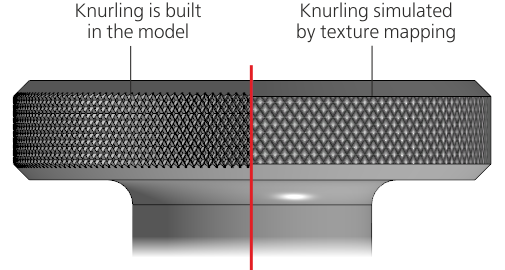
Using texture to imitate knurling
You can use textures to simplify models of components inserted in an assembly. For example, you can create a component detailing, in which complex elements are replaced by textures, and insert it into the assembly instead of the original component. For more details on working with layouts...
|
Using multiple different textures in a single model is not recommended. It can slow down working with this model. |

Texturizing is available for objects which have faces such as a solid, a component, etc. You can either set a texture for the entire object or for a separate face.
A set of raster images used for texturing objects is supplied with the KOMPAS-3D. In the course of the system installation they are placed in the \Sys\Appearance subfolder of the main system directory. Files with images are grouped by method of display in the model. Each group is located in a separate folder:
•Textures — images that simulate material texture,
•Reliefs — simulation of emboss on the surface,
•Cutouts — images simulating perforation.
More details about the methods of displaying images...
You can set existing textures for objects or create your own images to use them as textures. PNG, JPEG, BMP, GIF, TIFF, and TGA files can be used. If a user-defined texture is set for the model object, the file containing this texture should be included in the document bundle in case if the model is transferred to another workstation.

When you use textures, keep in mind the following:
•The selected image is shown on the object surface based on the set color.
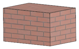
•If the object surface contains multiple faces, the selected image is separately overlaid on each face as if these are different objects. Due to this, pattern elements on junctures of faces may not coincide.
|
Textures are shown on the screen in case of the rendering model option Enhanced or Base (see section System control). |
There are various methods of showing the selected image on the screen. This enables simulation of the following characteristics of a surface:
•material texture,
•surface relief,
•perforation.
To ensure that the image is shown in the required way, it should be selected using the relevant field on the Parameter Toolbar. The fields and methods of images display are described in the table.
Methods of bitmap images display on the object surface
Image selection field |
Display method |
Image |
Example of usage |
|
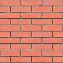
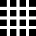
Texture |
Material texture simulation. The selected image is overlaid on the object surface. |
|
|
|
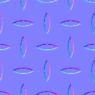
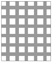
Relief |
Relief surface simulation. To show an image, use the Normal map. This method is used to change the normals of displayed pixels based on a color normal map. |
|
|
|
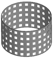
Cuts |
Perforated surface simulation. It is performed using an image which contains elements of dark (almost black) color. When the image is overlaid on the object surface, parts of the surface coinciding with the dark color elements are no longer displayed on the screen, creating an effect of a surface with multiple cuts. This method allows to reduce the number of draws in the model to simplify it — the cuts are not built but simulated using a bitmap image. Such a "light-weight" model is convenient to use, for example, as a Component mockup. |
|
|
If necessary, you can simultaneously select files for several display methods, for example, Texture and Relief, Relief and Cuts, etc. The selected images are overlaid on top of each other.
|
|
|
a) |
b) |
c) |

Images overlay
a) surface with texture, b) surface with cuts,
c) surface with texture and cuts
Procedure for setting a texture
1.Select the object you want to overlay an image on.
2.On the Parameter Panel in the Color section, click the icon  in the Optical Properties field. The process will start Graphic display of material.
3.Expand the Texture section of the Parameter Panel.
4.Click the name of the field corresponding to the required display method, for example, the Texture field. The screen will display the file selection dialog. By default, it shows the folder with standard image files included in the KOMPAS-3D package (see section Using textures in models).
5.Specify the file with the required image and click Open button.
The full file name will be shown in the Parameter Toolbar field and a phantom image will appear in the graphic area.
6.If necessary, select files for several display methods. The images will be overlaid (see the figure above).
7.After the image file is selected, elements used for setting parameters of the image location appear on the Parameter Panel.
Set the parameter values. To do this, click the button corresponding to the selected display method and enter the values in the relevant fields. For description of the fields, see the table.
If files are selected for several display methods and parameters of images location coincide, then instead of setting them for each image you can click All and enter the values once.
Image placement parameters
Name |
Description |
|
Width, % Height, % |
Fields for setting the image size by width and height — in fact, for setting the scale of the repeated texture part. Values are set as a percentage from the image size in the source file. If you need to maintain the proportion between the width and the height, click the Proportionally button |
|
Offset by horizontal line Offset by vertical line |
The fields for entering values of the image starting point offset along isoperimetric curves of the object surface. |
|
Rotation |
The field for setting the image rotation angle. The angle value can be entered manually or selected from the drop–down list. |

8.To complete editing the object, click Create an object  button.