|
Connection points setup |
Scroll |
When building a surface over a grid of curves, it is possible to customize the connection of points of curves in each direction, i.e., control the points through which will pass isoparametric curves of obtained surface. For clarity, in the figures of this section, surfaces are shown with their isoparametric curves.
Setting up the connection of points is performed in the Connection section. The controls of this section allow you to select the distribution option for connecting points along curves and explicitly specify the points that will be connected to each other as a result of surface construction.
Select distribution option of connecting points along curves
For selecting a distribution option for connecting points along curves, click the required button in the group Section Alignment:
 By the parameter of the guides — points located on the curves with equal step along the parameter of these curves will be connected. More details on parametric representation of the curve...
 Along the length of the guides — points located on the curves at equal intervals along the lengths of these curves will be connected.
The selected variant of point distribution applies to curves in both directions.
The figure shows examples of constructing a surface based on the same curves (marked in red color) but with different section alignments.
|
|
a) |
b) |
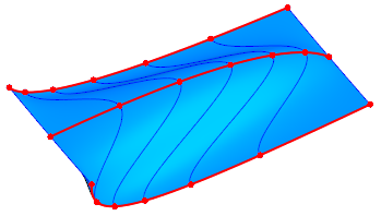
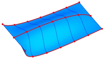
Surface, where the U directional curves are arcs of an ellipse (the V directional curves are not specified):
a) connected points are uniformly distributed along the parameter of the guides,
due to which they thicken in areas with greater curvature,
b) connected points are evenly distributed along the length of the guides
Indicating the connected points manually
By default, when creating a surface, the connected points of curves of the same direction will be determined automatically. You can define custom points and sonnect them manually i.e. create chains. The figure shows examples of plotting a surface based on the same curves but with different chains.
|
|
a) |
b) |
|
|
c) |
d) |
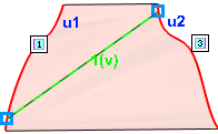
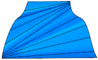
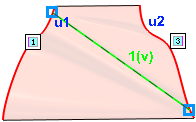
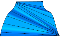
Example of plotting a surface by grid of curves using chains
a), c) phantoms of a surface with different positions of connected points,
b), d) respective design results
|
Selected variant for distributing points along curves — By the parameter of the guides or Along the length of the guides — works independently of the presence of chains. If there is no chain, then the distribution option is applied to the curves as a whole. If there are chains, they divide the curves into portions, and the selected distribution option is then applied to each portion. |

•Creating chains
To specify the connected points of curves manually, press the Add Chain button  to the right of the Chains (U)/(V) field. The button is displayed if at least two objects are specified for this direction. Pressing the button launches chain creation sub-process. Select the points to be connected. Create the proper number of chains.
A list of created chains is displayed in the Chains (U)/(V) field. The chain selected in the list is highlighted in the graphics area. If you want to display all the chains on the phantom, enable the option Show all in model window.
•Editing chains
To edit a chain, use one of the following methods:
•Select the chain row in the field Chains (U)/(V) and press the Edit Chain button  — it will start chain creation sub-process,
•change the positions of the chain points by dragging them in the graphics area.
•Deleting chains
To delete a chain, select the required row in the Chains field and press the Delete button  .
.