|
Plotting a connecting surface |
Scroll |
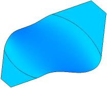
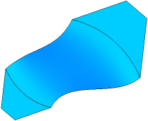
The connection surface boundaries are the specified edges or chains of edges of the joined faces.

To plot a connection surface, use the Connection Surface  command.
Step-by-step instructions
1.In the graphic area, select the border of the first mated surface: an edge or a chain of edges. The name of the selected edge(s) appears in the Edges (1) field in the Borders 1 group on the Parameters toolbar. The face with the selected edges is automatically selected as the mating surface. Its name is displayed in the field Surface(1).
2.You can change the face if the edge belongs to two faces at the same time. To do this, specify the desired face in the graphics area.
3.Select the condition of mating of the connecting surface with the first mated surface by pressing the corresponding button in the Condition 1 group:
 Not specified,
 By tangent,
 Smooth,
 Perpendicular.
For more details on mating conditions...
4.If necessary, change the direction of conjugation to the opposite using the Change Direction  button to the right of the Surface(1) field. If you do thus, the shape of the connection surface will change near the border but the mating condition remains the same.
5.Set the position of lateral edges of the new surface using the group of controls Lateral edges 1:
 By normal to border.
 As extension of original lateral edges.
6.Set the value of tension in the Tension 1,% field. This setting determines the shape of the surface: the higher is the tension, the greater is the curvature of the connection surface near the border; and vice versa: the lower is the tension, the lower is the curvature of the surface. Tension is set as percentage, a number from 0 to 100.
If the second border should have the same tension, please enable the Total tension.
7.Select the second border of the connection surface and set the connection parameters as described above using the Border 2 group of controls on the Parameter Panel.
A phantom of the connection surface with current settings is displayed in the graphic area. The second border may belong to the same face as the first one. The new surface will connect different flanges of the same face.
8.If you need to check the connection surface for self–intersections, please enable the Self-intersection check setting. If any self–intersections are detected, a corresponding message will appear on the screen. More details on surface self-intersection...
9.You can configure the splitting of the new surface into faces using the controls in the Splitting section. The splitting setting is similar to the Configuring splitting a ruled surface into faces.
10.You cat set the name of the connection surface and its display parameters using the controls in the Properties section on the Parameter Panel. Management of color and optical properties of objects...
11.To complete the operation, click Create an object  .
.
The connection surface will appear in the graphic area; its icon .
12.To complete operation of the command, click Finish  .
.
Tips
•You can specify the tension setting using the defining point.
See Also