|
Cam-pusher mating |
Scroll |
The Cam–pusher mating allows you to establish a relationship between movements in the cam mechanism. The cam makes a rotational movement, and the pusher is reciprocating. At the same time, the working surface of the pusher remains in contact with the working surface of the cam.
This mating is used to visualize the operation of cam mechanisms and similar models. It is overlaid on two components in a model.
Objects for mating are selected in such a way that one of them serves as a cam rotating around an axis, the other serves as a pusher moving along a straight path. The design of the mechanism should ensure the contact of the cam and the pusher within their working surfaces.
The cam is a single-solid part. The working surface of the cam may consist of one or several faces – flat, cylindrical, conical, or toroidal. Besides, the working surface of the cam can be a ruled surface whose sketch consists of segments, arcs, arcs of ellipses, splines.
|
Contact between objects is provided by the mechanism of cam-pusher mating. Therefore, it is not recommended to overlay a Tangency positioning mating on the cam and pusher; this will lead to an error in the cam-pusher mating. |

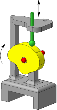
An example of applying the cam-pusher mating
The Cam-pusher  command is used to create the mating.

Step-by-step instructions
1.Specify the faces of the cam working surface that will be used in the mating. Face names appear in the Work Faces fields of the Cam control group on the Parameter Panel.
Below the Work Faces group there is an option Select tangent faces. This option is used to automatically select the smoothly mated edges of the cam working face.
•If this option is enabled, then specifying one face automatically selects also faces mating with the specified face and with each other along straight line segments parallel to the cam axis. The tangent faces are selected after specifying the cam rotation axis (see below).
Faces that are not connected with each are specified one by one.
•When the option is disabled, all the faces of the cam should be specified one by one.
2.Specify the cam rotation axis. To do this, click in the Axis field and specify the desired object in the graphic area. The name of the selected object is displayed in the Axis field.
After specifying the axis, the direction of rotation of the cam is automatically determined. This direction is indicated by circular arrows in the graphics area.
3.Specify the working face of the pusher. The following may be used as a working face:
•flat face,
•cylindrical face,
•spherical face,
•vertex in a pusher part.
The mating involves the surface obtained by extension of the specified face, either a plane, cylindrical surface or a complete sphere.
The name of the selected object will appear in the Work Face field of the Pusher group.
|
If the working surface of the pusher is flat, then only cylindrical, conical or ruled surface can serve as the working surface of the cam. In this case, the cam and the pusher should be oriented relative to each other in such a way that their tangency occurs in a straight line. |
4.Select the path of the pusher movement. As paths , rectilinear objects are used: segments of polylines, axes, rectilinear ribs. The name of the selected object will appear in the Path field. A phantom arrow in the graphic area indicates the direction of the pusher movement.
The working surfaces of the cam and the pusher come into contact.
5.To complete creating the mating, click Create object  .
.
After that, the mating is overlaid on the specified objects, and the corresponding icon appears in the Design Tree.
6.To complete operation of the command, click Complete  .
.
After creating a mating, you can view its work.
See Also