|
Rotation – Movement mating |
Scroll |
The Rotation-Movement mating allows you to establish a relationship between the rotation of one object and the movement of another. When the first object rotates, the second object associated with it moves along a straight-line path and vice versa – moving the second object makes the first one rotate.
This mating is used to visualize the operation of mechanisms in pinion-rack drives, screw-nut gears and others.
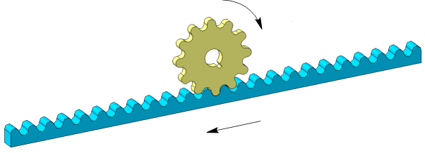
An example of applying the Rotation-Movement mating
To create a mating, use the Rotation-Movement  command.

Step-by-step instructions
1.Select the first component. Its name will appear in the Component group field Component 1 – rotation on the Parameters toolbar.
2.Select the axis of revolution of the first component. Its name will appear in the Axis field of the group Component 1 – rotation.
After specifying the axis, the direction of rotation of the component is automatically determined. This direction is indicated by circular arrows in the graphics area.
The rotation direction can be changed to the opposite by clicking the Change direction  to the right of the Axis field.
3.Specify the second component and the path that sets the direction of its movement. The names of the selected objects will appear in the Component and Path of the group Component 2 – movement.
The direction of movement of the object is indicated by an arrow in the graphic area. It can be switched to the opposite using the Change direction button to the right of the Path field .
4.Set the component movements ratio. To do this, enter in the Ratio field two real numbers representing the ratio of the circumference length of a unit radius, which equals 2π (mm), to the linear displacement of the second component.
The entered numbers can be swapped by clicking the Invert Ratio button  to the right of the Ratio field.
The 1:2 ratio means that during one revolution of the first object, the second object moves by 2×2π (mm), i.e. to approximately 13 mm.
If one object is fixed, then the ratio is calculated similarly. For example, the rail is stationary, and the wheel of radius R (mm) rolls along it without sliding. During one revolution of the wheel the rail moves relative to the wheel center by 2πR. The movement ratio is 1:R.
|
To calculate the ratio, you can use the formula 1:(L/2π). Here L is the distance in millimeters to which the second object must move in one revolution of the first object. |

5.To complete creating the mating, click Create object  .
.
After that, the mating is overlaid on the specified objects, and the corresponding icon appears in the Feature Tree.
6.To complete operation of the command, click Complete  .
.
After creating a mating, you can view its work.
See Also