|
Rotation – Rotation mating |
Scroll |
The Rotation-Rotation mating allows you to establish a connection between rotations of two objects, where rotation of one object leads to rotation of another object. It is overlaid on two components or on a component and a solid in a model, not necessarily in contact with each other.
This mating is used to visualize movement in models of gear, belt, chain, friction transmissions and others.
An example of applying rotation matings
The Rotation-Rotation  command is used to create a rotation joint.

Step-by-step instructions
1.Select the first rotating component. Its name will appear in the Component field of the Component 1 group on the Parameters toolbar.
2.Select the axis of revolution of the first component. Its name will appear in the Axis field of the Component 1 group.
After specifying the axis, the direction of rotation of the object is automatically determined. This direction is indicated by circular arrows in the graphics area.
The direction of rotation can be changed to the opposite by clicking Change Direction  to the right of the Axis field.
3.Similarly, specify the second rotating component and its axis of rotation. Their names will appear in the Component and Axis fields of the Component 2 group.
|
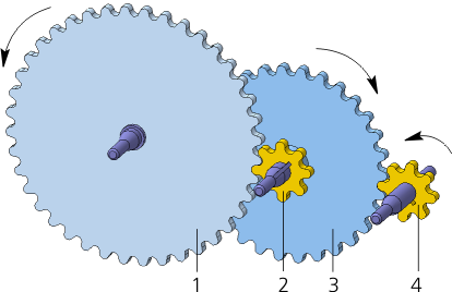
You cannot overlay a mate on a pair of objects that are on the same axis of rotation. In the figure, such objects are wheels 2 and 3. |

4.Set the component rotations ratio. To do this, in the Ratio field, enter two real numbers denoting the ratio of the number of revolutions of the first object to the number of revolutions of the second object.
The entered numbers can be swapped by clicking Invert Ratio  on the right side of the Ratio field.
The ratio is determined by analogy with the gear reduction ratio. For example, the ratio 1:2 means that during one revolution of the first object, the second object makes 2 turns.
If one object is fixed, then the ratio is calculated similarly. For example, one of two mating wheels is fixed. In this case, the movable wheel rotates around its axis with simultaneous rotation around the fixed wheel. The ratio is equal to the ratio of the number of revolutions of the movable axis around the fixed one to the number of revolutions of the movable wheel around its axis.
|
If you specify the revolution surface when selecting an object, then the revolution surface radius is sent to one of the Ratio field parts. Note that the radius of the first object is transferred to the second part of the field, and the radius of the second object is transmitted to the first part. |
In the example shown in the figure, you can overlay two rotation matings, between wheels 1 and 2 and between wheels 3 and 4.
5.To complete creating the mating, click Create an object  .
.
After that, the mating is overlaid on the specified objects, and the corresponding icon appears in the Feature Tree.
6.To complete operation of the command, click Finish  .
.
After creating a mating, you can view its work.
See Also