|
Elevation mark |
Scroll |
To build an elevation mark, do the following.
1.Run the Elevation mark  command.

2.Use the Variant for View group on the Parameter Panel to select the dimension variant.
3.Configure settings matching the selected variant. For a detailed description of actions required to set various variants of the base line, see below.
|
To preserve parameter settings for dimension text until the end of the current session, invoke the Remember caption command from the |


For the front view
This dimension variant is built with the Front  button pressed, and has the appearance shown in the figure.
To set a dimension, you need to set two level lines – Zero and Measurable. The base line value is calculated as the distance from the zero base line to the measurable base line. It is calculated in meters, accurate to a tenth. You can create a group of dimensions with values calculated based on the same zero base line.
|
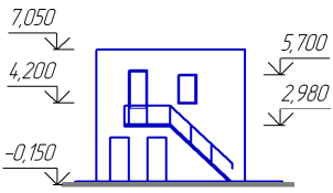
Setting the elevation label for the front view
1.Specify the zero base line point. In the graphic region, a phantom of dimension will appear.
By default, the dimension value is automatically defined by the system. At the same time, next to the Value field, the Auto  button has been pressed. As you move the cursor, the value changes automatically. These changes are displayed on the phantom and in the Text field on the Parameter Panel.
2.Specify the measurable base line point for the first dimension in the group. The dimension value will be fixed.
3.You can enter the dimension value manually, if required. To do this, press any alphanumeric key. This will start the subprocess of text input, allowing you to enter the required value and to configure text parameters. If you want to re-enable automatic definition of value, click Auto button.
4.For the value to appear underlined and/or in a marquee, enable the appropriate options.
5.Specify the point defining position of the dimension text. Dimension creation will be completed automatically.
6.Set the other dimensions in the group by specifying measurable base line points and dimension text positions.
7.To start setting a new group of dimensions, unfix the zero base line point.
8.To complete operation of the command, click Finish  .
.
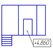
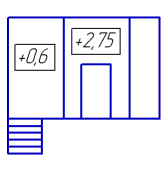
For the top view and the top view with leader
If With leader  button is clicked, the dimension is labeled on the landing (see fig. a), and if Top
  button is clicked, the dimension is labeled directly on the drawing (see fig. b).
|
|
a) |
b) |
Options for setting the base line:
a) for the top view with a leader, b) for the top view immediately in drawing
1.If you set a dimension on a landing (With leader option), specify the measurable base line point. If dimension is set directly on the image (Top View option), you don’t need to specify this point.
2.Values of these dimensions cannot be defined automatically. To enter a value manually or configure text parameters, click in the Text field and perform the necessary actions in subprocess of text input.
3.Dimension values will be displayed in a marquee. If you need to underline a value, enable the appropriate option.
4.Specify the point defining position of the dimension text. Dimension creation will be completed automatically.
5.Set all the other dimensions in the same way.
6.To complete operation of the command, click Finish .