|
Fill parameters |
Scroll |
Fill parameters are set using the Parameter Panel elements described in the table. The set of elements depends on the selected Fill Type. The description of the elements for monochrome and gradient fills is presented below.
Monochrome fill parameters
Monochrome Fill Controls
The element |
Description |
|
Color |
The field displays the current fill color. Drop-down list allows you to set the color. By clicking the Other colors line you can open the advanced color selection dialog. |
|
Transparency |
The scale allows you to set the transparency of selected color. To change transparency, move the slider with the mouse – to the right to increase and to the left to decrease the level of transparency. The current transparency in percent is displayed in the box to the right of the scale. This field is not available for manual entry. If the transparency is 0%, then the fill is completely opaque. At 100% transparency, the fill is completely transparent. |
|
|
Some output devices do not support printing transparent fill. In these cases, when setting up printing, it is recommended to include an alternative output method (see sections Advanced print settings and Print Settings). |

When creating gradient fills, consider the following features.
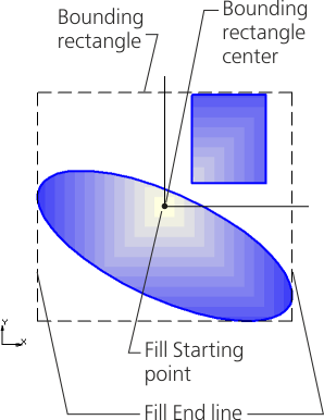
After specifying one or more fill areas around the contours, a bounding rectangle is automatically built, within which the color distribution occurs. When changing the parameters of the fill, for example, the angle of rotation, the bounding rectangle changes. Bounding rectangle is conditional and is not displayed in the graphic area.
|
|
a) |
b) |
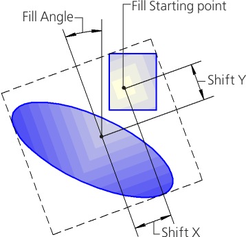
Fill options when building
a) in the absence of shear and angle of inclination, b) after setting the shift and angle of inclination
Fill Angle determines the rotation of the fill relative to the starting point within the region. When changing the fill angle, the bounding rectangle rotates to the specified angle.
Fill Starting point is the point at which the initial color is set. The position of this point can be changed by shift relative to the center of the bounding rectangle or contour. If there is no shift, then the starting point lies in the center of the bounding rectangle or contour.
Fill Starting line – the line passing through the starting point. From the starting line or starting beam, a color transition begins for some types of fill.
End line fill is the line or end beam in which the end color is set.
Gradient controls
The element |
Description |
|
Color transition scale |
Allows you to set fill colors, position of colors and transparency levels. Color markers are displayed at the bottom of the scale. Clicking a marker makes it current. The current marker is blue. After clicking the "+" icon in the middle of the scale, a new marker appears. By default, the color of the created marker is intermediate between the colors of the nearest markers. To change the position of the intermediate marker, move it with the mouse or enter a value in the Position field. The number of intermediate colors is not limited. |
|
|
Change Gradient Direction |
The button allows you to change the direction of the colors of the gradient to the opposite. |
Position |
The field displays the integer value in percent, which characterizes the position of the current marker relative to the starting point of the fill. Position 0 corresponds to the initial color, position 100 – the final color of the fill. The field is available if the current is an intermediate marker. |
|
|
Delete Marker |
The button allows you to remove the intermediate fill color. Present in the Parameter Panel, if the current is an intermediate marker. |
Color |
The field displays the color of the current marker. The drop-down list allows you to set the color. By clicking the Other colors line you can open the advanced color selection dialog. |
|
Interpolation |
The toggle switch controls the setting of intermediate levels of transparency in the fill. Present in the Parameter Panel, if the current is an intermediate marker. •If the toggle switch is in the I (enabled) position, then the transparency in the current position is automatically determined. Its percentage value is displayed in the box to the right of the Transparency scale. The amount of transparency is interpolated between the values in the nearest positions – before and after the current one. Manual transparency change is not available. •If the toggle switch is in position 0 (disabled), the value of the current transparency is set manually using the Transparency scale or fields to the right of the scale. |
|
Transparency |
The scale allows you to set the transparency of the current fill color. The percentage of transparency is displayed in the box to the right of the scale. If the transparency is 0%, then the fill in the current position is completely opaque. At 100% transparency, the fill in the current position is completely transparent. If the transparency is nonzero, then Color transition scale displays black and white cells, the brightness of which you can visually assess the level of transparency. To change transparency, move the slider with the mouse – to the right to increase and to the left to decrease the transparency level, or enter a value in the field to the right of the scale. For the initial and final markers, a change in transparency is always available. For intermediate markers, a change in transparency is available if the Interpolation toggle switch is set to 0 (disabled). |
|
|
Some output devices do not support printing transparent fill. In these cases, when setting up printing, it is recommended to include an alternative output method (see sections Advanced print settings and Print Settings). |
|
Angle |
Field to enter the value of the rotation angle of the fill relative to the starting point inside the area. Present in the Parameter Panel when creating all gradient fills except Radial gradient. To set the angle, use the geometrical calculator. |
|
|
Change sign |
The button allows you to change the sign in the angle value to the opposite. After clicking the button, the arrow on the icon will change. |
Offset |
Fields for entering the relative displacement of the initial fill point from the center to the sides of the dimensional rectangle. Present in the Parameter Panel when creating all gradient fills except the linear gradient. For Cylindrical gradient is specified the starting point offset to the starting or ending fill line. The offset can take values from -100 to 100%. •If the values are set to 0%, then there is no offset – the starting point of the fill coincides with the center of the bounding rectangle or contour. •A value of 100% offset along the X axis or Y axis means that the starting point of the fill lies on the side (contour) of the dimensional rectangle. |
|
Color gradients |
A group of buttons allows you to select how to change the fill color from the initial to the final color: •Continuous – color transition is performed smoothly, •Step by step – color transition is performed in the number of steps entered in the field Number of steps. |
|
|
||
|
||
Number of steps |
The field for entering the number of steps for changing the fill color is from 1 to 255. Appears on the Parameter Panel if Step by step method is selected to change the color. |


|
|
a) |
b) |
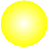
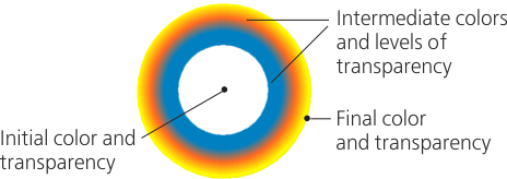
Radial fill before and after adding multiple colors and transparency levels