|
Geometrical calculator for graphic objects |
Scroll |
In the graphic document there are the following geometrical calculator command groups available:
Objects to read out parameters from can be any lines and texts, including those contained in dimensions, designations, macro-elements, fragment inserts and views.
|
The size of the cursor’s trap can be changed in the dialog for setting up the cursor. |

Example of using the geometrical calculator for graphic objects...
Geometrical calculator for coordinates
Command |
Command purpose and step-by-step instructions |
|
Readout of coordinate values of the point located at the intersection of curves extensions or at the intersection of one curve with the extension of another. The intersection points of objects themselves are not processed. An extension can be constructed for line segments, circular arcs and ellipses. 1.Click on the first curve – it will be highlighted; if the curve can be extended, its extension will be displayed on the screen. 2.Hover the mouse cursor over the second curve – it will be highlighted, the curve extension (if it can be extended) and points of intersection with the first curve will be displayed on the screen. 3.Click on the second curve. After that: •if there is only one point of intersection, its coordinates are calculated and passed into the Parameter Panel fields, •if there are multiple points of intersection, then specify the desired point. |
||
At distance from point |
Readout of coordinate values of the point that is offset from the base point to the given value. 1.Click the base point, i. e. the point the offset will be measured from. 2.Enter any two of the parameters. •After entering the first parameter, it is displayed on the screen as a straight line parallel to the coordinate axis, or as a radius vector of the given length, or as the radius vector direction. •The second parameter can be specified both by entering the value in the Parameter Panel and by specifying the point in the graphic area. The offset point coordinates are calculated and passed into Parameter Toolbar fields. Tips and Tricks: •To specify points, you can use snaps. •If the command is invoked for a fixed point, this point is considered the base one (i. e. you don’t need to specify the base point). Thus you can specify the new position of the point relative to its previous position. |
|
At distance from two curves |
Readout of coordinate values of the point located at the given distances from the specified curves. The point is found as the intersection of equidistant lines of the specified curves. Equidistant lines of straight line segments are infinite, equidistant lines for the rest of elements have no extension. 1.Enter distances from the curves to the point being created. 2.Click on the first curve – it will be highlighted, its equidistant lines will be displayed on the screen. 3.Hover the mouse cursor over the second curve. 4.Click on the second curve. After that: •if there is only one point of intersection of the equidistant lines, its coordinates are calculated and passed into the Parameter Panel fields, •if there are multiple points of intersection of the equidistant lines, then specify the desired point. The found point coordinates are calculated and passed into Parameter Toolbar fields. Tips: •To cancel the curve selection, remove it from the Objects list. •You can change distances from curves to the point before clicking on the second curve. |
|
Readout of coordinate values of the point aligned by two other points. A point is considered aligned by two other points if they are its projections on the current CS axes. 1.Click the first point, and then the second one of those used to align by. The points should not lie on the same axis of the current CS. 2.Hover the cursor over the desired variant and click. The found point coordinates are calculated and passed into Parameter Toolbar fields. Tips: •To specify the points from the start, unfix the First point and Second point fields on the Parameter Panel. •To specify points, you can use snaps. |
||
|
nearest to another zurve |
Readout of coordinate values of the point which is located on one curve and nearest to the other curve. 1.Click on the first curve – where the point should be located. 2.Click on the second curve – to calculate the minimum distance to. There is a point on the first curve which is the nearest one to the second curve, the coordinates of the found point are determined and passed into the Parameter Toolbar fields. |
|
|
Intersection |
Readout of the coordinate values of the point located at the intersection of curve extensions with construction of the conditional intersection. The intersection points of curves themselves are not processed. You can specify the following curves: line segments, circular and elliptical arcs, equidistant lines of segments and of circular arcs. 1.Click on the first curve – it will be highlighted. 2.Hover the cursor over the second curve. •If there is at least one construction variant for the given pair of curves, this curve is highlighted and the conditional intersection phantom appears. •If there are two intersections, the system displays the variant which is closer to the point of specification of the second curve. To display the other variant, move the cursor to the other end of the curve.
3.Click on the second curve. The current conditional intersection phantom is fixed, the point coordinates are determined and passed into the Parameters Panel fields. |
Geometrical calculator for linear values
Command |
Command purpose and step-by-step instructions |
|
Readout of the element length (perimeter) value. 1.Hover the cursor over the object whose length or perimeter you need to determine – the object will be highlighted. 2.Click the left mouse button – the object length value will be calculated and passed into the Parameter Panel field. |
||
Readout of length of a segment of a broken line or contour, as well as a polygon side. 1.Hover the cursor over the segment whose length you need to determine – the whole object will be highlighted. 2.Click the left mouse button – the segment length value will be calculated and passed into the Parameter Panel field. |
||
Readout of distance value between two specified points. 1.Click the first point. 2.Click the second point – the distance between the points will be calculated and passed into the Parameter Panel field. |
||
|
on curve |
Readout of length of a curve portion limited by two points of that curve. 1.Click on the curve whose portion length you need to determine. 2.Click the first point that limits the curve portion. 3.Click the second point – the length of the curve portion between the points will be calculated and passed into the Parameter Panel field. |
|
Readout of distance between the nearest points of the specified curves. 1.Click on the first curve. 2.Click on the second curve – the distance between the nearest points of the curves will be calculated and passed into the Parameter Panel field. |
||
|
to a curve – By Normal |
Readout of the shortest distance value between the specified point and curve. 1.Click the point. You can use a snap. 2.Click on the curve – the shortest distance between the point and the curve will be calculated and passed into the Parameter Panel field. |
|
|
To Curve — By Y |
Readout of the distance value between the specified point and object in the positive direction of the Y axis of the current coordinate system. 1.Click the point. You can use a snap. 2.Click on the curve – the distance between the point and the curve along the Y axis of the current coordinate system will be calculated and passed into the Parameter Panel field. |
|
From a Point |
Readout of the distance value between the specified point and object in the negative direction of the Y axis of the current coordinate system. 1.Click the point. You can use a Snaps. 2.Click on the curve – the distance between the point and the curve against the Y axis of the current coordinate system will be calculated and passed into the Parameter Panel field. |
|
|
To Curve — By X |
Readout of the distance value between the specified point and object in the positive direction of the X axis of the current coordinate system. 1.Click the point. You can use a snap. 2.Click on the curve – the distance between the point and the curve along the X axis of the current coordinate system will be calculated and passed into the Parameter Panel field. |
|
|
To Curve — Against X |
Readout of the distance value between the specified point and object in the negative direction of the X axis of the current coordinate system. 1.Click the point. You can use a snap. 2.Click on the curve – the distance between the point and the curve against the X axis of the current coordinate system will be calculated and passed into the Parameter Panel field. |
|
Readout of the diameter value of the specified circle or arc. 1.Hover the cursor over the circle or arc whose diameter you need to determine – the object will be highlighted. 2.Click the left mouse button – the diameter value will be calculated and passed into the Parameter Panel field. |
||
Readout of the radius value of the specified circle or arc. 1.Hover the cursor over the circle or arc whose radius you need to determine – the object will be highlighted. 2.Click the left mouse button – the radius value will be calculated and passed into the Parameter Panel field. |
||
Readout of the major semi–axis length value of the specified ellipse (or elliptical arc). 1.Hover the cursor over the ellipse or elliptical arc whose major semi–axis value you need to determine – the object will be highlighted. 2.Click the left mouse button – the semi–axis length will be calculated and passed into the Parameter Panel field. |
||
Readout of the minor semi–axis length value of the specified ellipse or elliptical arc. 1.Hover the cursor over the ellipse or elliptical arc whose minor semi–axis value you need to determine – the object will be highlighted. 2.Click the left mouse button – the semi–axis length will be calculated and passed into the Parameter Panel field. |
||
Text Line Length |
Readout of the text line length. 1.Hover the cursor over the text line whose length you need to determine – the object will be highlighted. 2.Click the left mouse button – the line length will be calculated and passed into the Parameter Panel field. |
|
Readout of the horizontal object size. In a drawing, horizontal is a direction parallel to the X axis of the coordinate system of the view containing the object, in a fragment and sketch — the X axis of the absolute coordinate system. 1.Hover the cursor over the object whose horizontal size you need to determine – the object will be highlighted. 2.Click the left mouse button – the horizontal size value will be calculated and passed into the Parameter Panel field. |
||
Readout of the vertical object size. In a drawing, vertical is a direction parallel to the Y axis of the coordinate system of the view containing the object, in a fragment and sketch — the Y axis of the absolute coordinate system. 1.Hover the cursor over the object whose vertical size you need to determine – the object will be highlighted. 2.Click the left mouse button – the vertical object size value will be calculated and passed into the Parameter Panel field. |
Geometrical calculator for angular values
Command |
Command purpose and step-by-step instructions |
|
Readout of the angle value between the specified straight line or segment and the positive direction of the X axis of the current coordinate system. 1.Hover the cursor over the object whose direction you need to determine – the object will be highlighted. 2.Click the left mouse button – the angle value will be calculated and passed into the Parameter Panel field. |
||
Readout of the angle value between the tangent line to the specified curve which goes through the specified point of this curve, and the positive direction of the X axis of the current coordinate system. 1.Click on the curve. 2.Click the curve point where the tangent line should go through. You can use a snap. |
||
Normal Slope |
Readout of the angle value between the normal line to the curve which goes through the specified point of this curve, and the positive direction of the X axis of the current coordinate system. 2.Click the curve point where the normal line should go through. You can use a snap. If a straight–line object was specified, you don’t need to specify the point. |
|
Readout of the aperture angle of the circular arc. 1.Hover the cursor over the arc whose aperture you need to determine – the arc will be highlighted. 2.Click the left mouse button – the aperture angle value will be calculated and passed into the Parameter Panel field. |
||
Readout of the angle value between two straight lines or segments. 1.Click on the first object. 2.Click on the second object – the angle between the objects will be calculated and passed in to the Parameter Panel field. |
||
Readout of the angle value between the major axis of an ellipse (or elliptical arc) and the positive direction of the X axis of the current coordinate system. 1.Hover the cursor over the ellipse or elliptical arc whose axis slope you need to determine – the object will be highlighted. 2.Click the left mouse button – the axis slope angle value will be calculated and passed into the Parameter Panel field. |
||
|
(with X Axis) |
Readout of the angle value between the straight line going through two specified points, and the positive direction of the X axis of the current coordinate system. 1.Click the first point. 2.Click the second point. To specify exact points, you can use snap. |
|
Readout of the value of angle constructed by three specified points. Sequence of specifying: the angle vertex, the side points of the angle. 1.Click the angle vertex. 2.Click the point on the first side of the angle, and then click the point on its second side. To specify exact points, you can use snap. |
||
Readout of the angle value between the specified text line and the positive direction of the X axis of the current coordinate system. 1.Hover the cursor over the text line whose slope angle you need to determine – the object will be highlighted. 2.Click the left mouse button – the slope angle of the line will be calculated and passed into the Parameter Panel field. |
||
Readout of the angle value between the radius plotted from the center of a circle (arc) to the specified point on it, and the positive direction of the X axis of the current coordinate system. 1.Click on the circle or arc. 2.Click a point on the circle or arc. You can use a snap. |
Geometrical calculator for scales
Command |
Command purpose and step-by-step instructions |
|
Readout of the ratio of lengths of two specified curves. 1.Click on the first curve. 2.Click on the second curve – the ratio of the first curve to the second one will be calculated and passed into the Parameter Panel field. |
||
Readout of the ratio of radii of two specified arcs or circles or an arc and a circle. 1.Click on the first arc or circle. 2.Click on the second arc or circle – the ratio of the first radius to the second one will be calculated and passed into the Parameter Panel field. |
Example of using the geometrical calculator
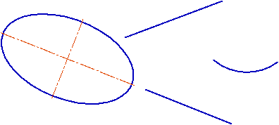
Consider applying the geometrical calculator using the example of constructing an ellipse whose center is located at the intersection point of the extensions of segments, its axis is parallel to one of the segments, and the semi–axis length is equal to the arc length (see figure).
|
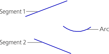
Objects whose parameters will be used by the Geometrical Calculator
Create a new graphic document and construct there objects shown on the figure, keeping proportions approximately. Then perform the following actions.
1.Invoke the ellipse construction command.
The Parameter Toolbar will display the fields to enter the ellipse parameters – the center coordinates, the semi-axes end coordinates, the semi-axes lengths and the first semi-axis slope angle.
2.Click the triangle to the right from the Center field name, call the Geometrical calculator menu and select the At intersection of curves' extensions command from it (see figure).
|
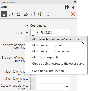
Geometrical calculator menu for coordinates (i.e. when specifying the point)
The Geometrical calculator subprocess will launch.
3.Specify the first and the second segment, whose extensions intersection should plot the ellipse center. The segment extension intersection point will be plotted automatically.
The Geometrical calculator subprocess will terminate, the system will return to the ellipse construction process.
The point coordinate value is calculated, written to the Center field and fixed.
4.Call the Geometrical calculator menu for the first ellipse axis slope angle and select the Line/Segment Direction command from it, and then specify the segment to which the first ellipse axis should be parallel.
The slope angle value of this segment to the OX axis of the current coordinate system will be calculated, written to the Angle field and fixed.
5.Call the Geometrical calculator menu for the first ellipse axis length and select the Curve Length command from it, and then specify the arc to whose length the ellipse semi–axis length should be equal.
The length value will be calculated, written to the Major Semi-Axis Length field and fixed.
6.Set the minor semi–axis length arbitrarily.
This completed construction of the ellipse with given parameters (see figure).
|