|
Building bend lines |
Scroll |
The Fold lines switch is used to construct bend lines on bends being unbent.
To create bend lines, set the toggle switch to I (enabled), set the The color and line style using the group of elements Displaying.
When the unbending operation is complete, lines of the given style and color will appear on the internal faces of the unbent bends. If a bend is divided into several parts as a result of constructing a cut or a strengthening edge, then for each part of the bend a separate line is built.
Bend lines are spatial curves. In the Design Tree bend lines are displayed on branches of their source objects — operations in which they were created. Each line is automatically named. Its name contains the sequential number of the bend line in the appropriate operation.
|
|
a) |
b) |
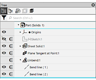
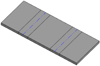
Example of displaying of bend lines creates in operation Flatten:
a) in the Design Tree, b) in the graphic region
Between the bend being unbent and the bend line an associative link is formed. If the bend later changes its position and/or parameters, the line of that bend will be shifted too.
Created bend lines can be used as objects to label dimensions and designations, and as objects for constructions.
Editing bend lines is impossible.
Bend lines created by the Unfold operation are handed over to the associative drawing of the sheet part if curve transfer is enabled.
|
After bending the unbent bends using the Fold command, the bend lines do not change their position and remain in the plane that was specified as the fixed plane during the execution of the Unfold operation. If necessary you can make any bend lines invisible: hide them or move to a hidden layer. More about managing visibility of objects... |
