|
Measurement of distance in the specified direction |
Scroll |
You can measure the distance along the required direction. This allows you to determine, for example, the minimum distance between objects, the overall dimension, or the center-to-center distance. You can use an edge, plane, or other as a guiding object. Straight-line or plane object. A straight-line object sets the direction parallel to itself, and a flat object – perpendicular. To specify the direction, you can also use a rotation surface (except for the sphere); the measurement direction will be parallel to the axis of the surface rotation.
The result of the measurement is the length of the projection of the distance between objects on the measurement direction or the value of the projection gap. The projection gap is measured between the projections of the selected objects in the measurement direction. When the guiding object is selected, additional objects showing how the measurement result was obtained are displayed in the graphics area on the phantom of the measurement.
The methods of measuring clearance and projection distance between objects are presented below. In figure a) a schematic of measuring the minimum projection clearance is shown, and in figure b) — a schematic of measuring the projection of the distance. As measurement objects, bodies 1 and 2 are selected, and the measurement direction is defined by a segment.
|
|
a) |
b) |
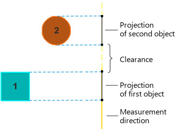
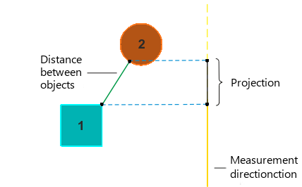
Distance measurement schemes in a given direction: a) gap, b) projection
In the figure, an example of measuring distance between objects of the model in the specified direction is shown. The distance between faces 1 and 2 is measured in the direction defined by a plane coinciding with face 2; option Briefly disabled on the Parameters Panel, in table of measurement results Selected lines L(min), L(max), and L(axis).
|
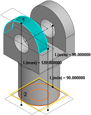
Measuring distance between objects in the specified direction.