|
Datum plane of dimension |
Scroll |
Datum plane of linear dimension
To label a linear dimension, it is required to set a base plane – a flat object parallel to which the plane of dimension will be located.
The base plane can be set in the following ways:
•automatically,
•indication of an existing object.
Automatically
If the dimension is labeled for a rectilinear edge or segment in the sketch, then the base plane is detected automatically. In the first case, one of flat faces to which the edge belongs is used, and in the second case – the plane of sketch is used.
The name of the base plane is displayed in the field of the same name in the Parameter Panel. If necessary, the automatically selected plane can be replaced using the method described below.
In some cases, you cannot replace the selected plane; the Base Plane field is not displayed on the Parameter Panel. For example, this may happen in the following cases:
•Dimension is labeled between rectilinear and point objects, with the plane running through these objects used as the base plane, see the figure below.
•Dimension is labeled between the axes of cylindrical/conical faces, with the plane running through the axes used as the base plane.
|
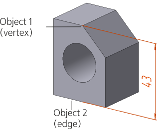
Linear dimension between the rectilinear and point objects
Specifying an existing object.
As the base plane, any flat object existing in the model can be used.
To select an existing object as the base plane, click the Base plane filed in the Reference objects section in the Parameter Panel and specify the required object on the Design Tree or in the graphic region. The name of selected object will appear in the specified field.
The base plane determines not only the spatial position of a dimension, but its value as well. As an example, we consider labeling dimensions between point objects in the model shown in the figure.
|
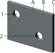
Point objects and possible base faces for labeling the dimension
To create a dimension, points 1 and 2 belonging the face A and located at the centers of round edges are specified.
•Figure a represents an example whose base plane is face A. Since this face contains both points 1 and 2, it is also a plane for labeling a dimension. The value of dimension equals the actual distance between points 1 and 2.
•Figure b represents an example whose base plane is face B. The plane for labeling a dimension is parallel to this face and runs through point 1. Point 2 is projected onto the dimension placement plane. The value of the dimension is equal to the distance from point 1 to the projection of point 2, i.e. the length of projection of the actual distance between points 1 and 2 onto the base plane.
•Figure c represents an example whose base plane is face C. The order of its building is the same as that of the previous one.
|
|
|
a) |
b) |
c) |
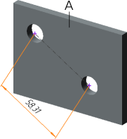

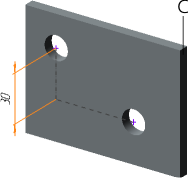
Dependence of the position and dimensional value on selection of the base plane:
a) base plane – face A; b) base plane – face B; c) base plane – face C
Datum plane of radial and diametric dimensions
After the indication of the object for which a dimension is labeled, the position of the base plane of the dimension is determined automatically.
•On selection of arc in the sketch, the dimension is labeled in the sketch plane.
•When selecting an edge in the form of an arc, the dimension is labeled in the plane of this edge (Figs. a, b).
•When selecting a face, the dimension is labeled in the plane perpendicular to the axis of the selected face and passing through the point at which the face is indicated (Figs. c, d). The circle for which a dimension is labeled is displayed with a dash-and-dot line with two points. The leader lines – with hatched lines.
|
A circle for which the size is labeled and leader lines are displayed, if in the dialog for setting up the dimensions and designations display The option Connector Lines is enabled. |

|
|
a) |
b) |
|
|
c) |
d) |
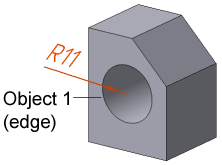
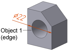
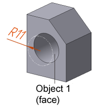
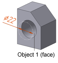
Radial and diameter dimensions:
a, b) to the edge in the form of a circle; c, d) to the cylindrical face
If the dimension is labeled for a face, then its position can be changed by linking to an object available in the model. In this case, on the Parameter Panel the Alignment field is present.
To replace the base plane, click inside the Alignment field. Then specify a point or flat object in the graphic region. Selection of object depends on the type of face for which a dimension is labeled.
•Cylindrical face
As the object of fixation, any point object or a flat object, perpendicular to the cylinder axis, can be selected.
•Conical face
As the object of fixation, any point object or a flat object, perpendicular to the cone axis, can be selected. The value of dimension matches the value of the radius (diameter) of intersection of the cone by a plane for labeling the dimension. As the plane of dimension is biased along the cone axis, the value changes accordingly with the change of value of the radius (diameter) of intersection of the cone.
|
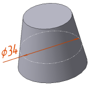
Diameter dimension to the conical face
•Spherical face
The initial position of a plane is determined automatically: the dimension is labeled in the plane that runs through the center of sphere and the point at which the face was specified.
As the object of fixation, any point or a flat object in the model can be selected.
On indication of a point object, the dimension is labeled in the plane that runs through center of the sphere and the selected point object; the position of the plane is determined by the system. On indication of a flat object – in the plane running through the center of the sphere parallel to the selected flat object.
|
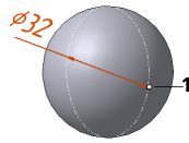
Diameter dimension to the spherical face
•Toroidal face
The dimension is labeled in the plane perpendicular the axis of face (the circular axis of the torus) and running through the point at which the face was specified.
As the object of fixation, any point object or a flat object perpendicular to the circular axis of torus can be selected.
|
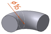
Diameter dimension to a toroidal face
After indication of the object of fixation, its name will appear in the Alignment field.
Between the dimension and the specified object, an associative link is established. Due to that, the dimension will follow the object when its position changes.
If the dimension is not fixed, you can change its position when you edit this dimension using a defining point.