|
Overview |
Scroll |
Any bend in the sheet part can be folded or unfolded.
You can use the following commands to change the bend state:
•Expand and Fold from the context menu of the sheet element in the Design tree,
•Expand and Fold from the Modelling – Sheet modelling menu.
There is a special sheet part display mode – a flat pattern view.
Working with the specified commands is described in detail later in this section.
|
Die forms, beats and louvers result from material deformation operations rather than bending. Die forms, beats and louvers do not contain bends and, therefore, these elements cannot be unfolded. |

Bend Unfolding and Folding
The Expand and Fold commands from the context menu of the sheet element allow you to change the state of all bends of this element. The icon of the unfolded sheet element is marked in the Design tree with an "unfolded" sign.
You can unfold any folded bend (or several bends) using the Expand command, and fold any unfolded bend using the Fold command from the Modelling – Sheet modelling menu.
You can apply these methods of managing the bend state at any time when creating a sheet part. However, they have different ways of operation.
Use of the first pair of commands means editing of an individual element: the states of bends included in this element change. The second pair of commands means editing of a sheet part as whole: the Unfold or Fold operation is added.
Note that editing of sheet elements using the Expand and Fold commands from the context menu may result in errors in objects derived from these elements (holes, cuts, etc.).
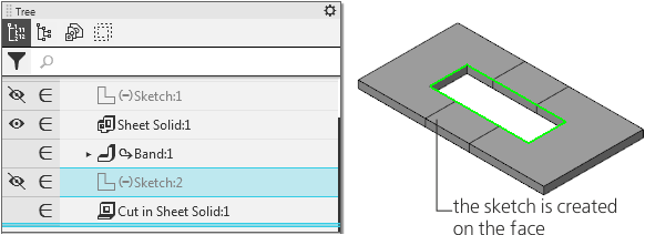
For example, a bend was created in the sheet part. The state of the bend was changed using the Expand command from the context menu. On the outer or inner face of the unfolded bend, a sketch was built based on which a cut is built by using the By thickness method (see figure a).
After the state of the bend was changed, i.e. after it was folded, the cut will show an error message "Sketch must be placed either on the outer or on the inner flat face of the sheet solid only" (Fig. b). This error occurs because the flat face on which the sketch was built becomes cylindrical after bend was folded.
|
a) |
|
b) |
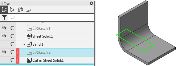
Example of an error in a sheet element as result of the changed bend state
Editing sheet elements using the Expand and Fold operations will not result in errors. However, such editing increases the total number of operations in the model and, therefore, its processing time (time required to open a file, rebuild a model, create associative views, etc.).
So, if a sheet element has no derivative objects (you can check this by using, for example, the Relationships command), you can change its state using commands from the context menu. Otherwise, use commands from the Modeling – Sheet Modeling menu.
|
If you know that certain bends should be unfolded in order to create specific elements, comply with the following working procedure. 1.Build sheet elements and unfold them using the Expand command from the context menu. 2.Build derivative objects from the sheet elements. 3.Fold bends using the Modeling – Sheet Modeling – Fold command. This scheme allows not to implement an additional unfolding operation. |

Sheet Part Display in Flat Pattern View
To display a sheet part in unfolded view, the Expand command  is used.
In the flat pattern mode, the selected bends are displayed in the folded state, all other bends – in the unfolded state. To switch to the flat pattern mode, you should configure the flat pattern parameters.
The states of bends established during editing of a sheet part are ignored when switching to the flat pattern display mode.
In the flat pattern mode, you can view a model, measure its geometric and mass-inertia properties, label dimensions and designations to the model objects. You cannot edit a model in the flat pattern mode.
See Also