|
Specifying bends |
Scroll |
You can specify the following objects in the graphic area to specify the position of bends when converting a model to a sheet solid:
•straight edges between the planar faces of the source model,
•cylindrical fillets between the flat faces.
The specified edges should belong to flat faces participating in the construction of the sheet solid, while fillets should be adjacent to such faces.
The following cannot be used for specifying bends:
•edges divided into parts as a result of designing other elements,
•cylindrical faces that are not smoothly joined with adjacent flat faces,
•cylindrical faces that do not have an adjacent planar face,
•cylindrical faces mated to non-flat faces.
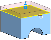
To define the first bend, select the straight edge of the base face or an adjacent fillet. A bend with an adjacent flat face — a bend extension.
|
|
Specifying the rectangular edge of the bend and phantom of the bend |
|
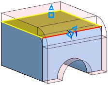
In sequence specify the edges and/or fillets that define the position of the bends in the sheet solid.
Bends are numbered in the order they are specified. The bend numbers and their corresponding parameters are placed in the table of the bend parameters (see below).
The system can automatically select fillets between the flat faces of the source model for unique determination of the bends position in the sheet solid. To do so, use Auto  button, located above the table Bends.
After pressing the button, bends and bend chains adjacent to the base face will appear on the sheet solid phantom with their corresponding extensions, and new rows will be added to the Bends table. Bends can form a chain if, for example, another bend adjoins a flat face adjacent to a bend, and one bend adjoins its extension , etc.
Bend parameters table
Each bend is characterized by a set of parameters. Their values are displayed in the Bends table on the Parameters Panel.
Table rows contain the following parameters of bends:
•a method for setting the radius,
•a radius value,
•value for the flat pattern parameter.
The number of rows in the table correspond to the order they are specified. Each row contains the parameters of one bend. When you specify a new bend, a new row will be created for it in the table.
The bend parameters table allows the following operations:
•Viewing bends
When you select a row in the table, the corresponding edge or fillet will be highlighted in the graphic area.
•Edit parameters of individual bends
Changing the bend parameters individually is available if the Unified/Individual switch, located in the Bend Parameters group, is set to Individual. Details...
•Delete bends
To delete a bend, you can:
•select a bend row in the table and click the Delete  button located above the table (the button appears after the row is selected),
•re-specify a bend in the graphic area.
Once removed, the bend will disappear and the sheet solid phantom will be rearranged. If you delete one of the bends that make up the chain, all subsequent bends will be deleted automatically.