|
Jogged Radial Dimension |
Scroll |
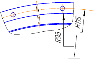
A jogged radial dimension is used when it is necessary to dimension an arc of very small curvature. In this case, the dimension line is a broken line and its segment that ends with the dimension arrow coincides with the true radius drawn to the selected point on the arc. The figure shows an example of setting the jogged dimension.
|
To build a jogged radial dimension, follow these steps.
1.Run the Jogged Radial Dimension  command.

2.Specify a circle (or circle arc) to be dimensioned. Its name will be displayed in the Object field, and the graphic area will display a phantom of the dimension.
3.Edit the dimension text, if required. To start working with the dimension text, press any alphanumeric key. See section on editing the dimension label...
4.Set the number of decimal places in the dimension text. Details...
5.Set a dimension tolerance. Details...
6.Set up additional dimension parameters, if required: dimension text placement option, arrow display parameters, etc. Details...
7.Set the point defining the dimensional line location. The point can be specified inside or outside the circle.
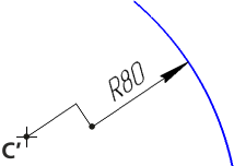
•If you select fixed or manual placement of the dimension text, the specified point also defines the text position (see Fig. a).
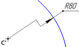
•If you select to place the dimension text on the landing, the point defines dimensional line location and the landing start (see Fig. b).
|
|
a) |
b) |
a) with auto-placed text; b) with text on the landing
8.Set the position of the dummy center of the circle located closer to the arc than the actual center. The dummy center is marked as the C’ point on Figures.
After the dummy center is specified, dimension is created automatically.
9.To complete operation of the command, click Finish  .
.
|
If you need to set multiple dimensions with a common dummy center to concentric arcs or circles, create such dimensions in a row, without exiting this command. In this case, the dummy center point for each subsequent dimension will be auto-created as matching the point set for the first dimension. |

Notes on editing the dimension line
You can edit jogged dimension line by changing the position of its defining points using the mouse in the graphic area of the document. To do this, you need to select the dimension and move its defining points. Practices of handling defining points...
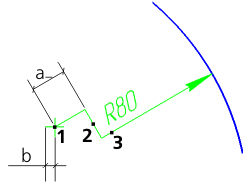
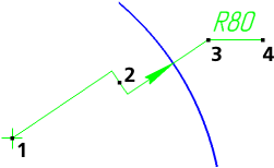
Jogged dimension line has the following defining points:
1 – point to change position of the dummy center,
2 – point to offset the bend along the dimension line,
3 – a point to change the slope angle of the dimension line; for a dimension line with dimension text placed manually or on the landing, point 3 can also be used to move the text or the landing,
4 – point to change landing direction.
The number and location of defining points depend on the method of text placement.
|
|
a) |
b) |
Defining points for the dimension with text placed
a) manually, b) on the landing
When you move the bend point, you must remember that the length of the line from the center to the bend point is limited by the dimension of the dummy center designation, i.e., a>b (see Fig. a).
To change the default size of the center line in the current document, go to Settings - Parameters... and in the left part of the dialog box that appears, select Current document — Centerline.
|
This section describes how the dimension can be modified without starting the editing process. For details on how to work with dimension defining points in the editing mode, see Section Changing dimensions in the editing process. |
