|
Initial alignment |
Scroll |
Position and the shape of the objects being combined affect the result of the alignment. In some cases, for example, if the objects are located far from each other, it is impossible to obtain an accurate combination in one operation. To improve the result of the combination, use Initial alignment.
The initial alignment is a preliminary «rough» alignment of the polygonal object with the model object. Then the main alignment algorithm is applied to the objects — the iterative closest points algorithm.
The pre-alignment method is selected from the list Initial alignment. The following options are available:
•According to inertial characteristic (default option),
•In arrow direction and point.
The choice of alignment method depends on the shape and relative position of the objects being combined.
Combination without initial alignment consists of the fact that the main algorithm of combination is applied to objects immediately. This happens if the list Initial alignment line selected Do not perform.
Correct alignment results without prior alignment are achieved when objects are located fairly close to each other and have similar elements that are also located close to each other. In all other cases, it is recommended to use alignment.
Example
It is necessary to combine a polygonal object obtained by scanning a product Cap, with the body built in the original model of this product.
The objects being combined have similar shapes and are located close to each other.
|
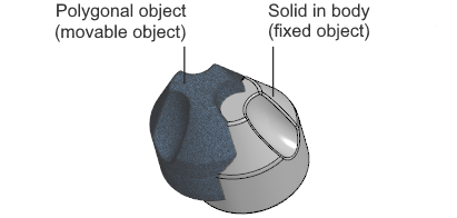
Appearance and initial position of the objects to be combined
By default, the alignment is performed with inertial alignment (this alignment method is described below). For objects with radial symmetry, as in our example, this alignment does not work the best. When viewing the result, it is clear that in many areas of the body surface there is no match with the polygonal object phantom (Fig.The process of alignment, and the phantom is shown in pink).
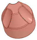
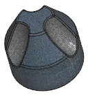
For a more accurate combination, we will select the option Without alignment When viewing the result, it is clear that the phantom matches the body (Fig.The process of alignment,b).
Let's confirm the alignment. The polygonal object has taken the place of the phantom (Fig.The process of alignment,c) The result of the combination satisfies the requirements.
|
|
|
a) |
b) |
c) |
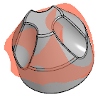
The process of alignment:
a) viewing the result of the combination performed with alignment according to inertial characteristics,
b) viewing the result of the alignment performed without alignment,
c) the result of combining objects without alignment
Alignment by inertial characteristics
Alignment method According to inertial characteristics consists of combining the principal axes of inertia of objects and their centers of mass.
This method gives a good effect if the objects are far from each other, have a similar shape and do not have a pronounced symmetry. For objects with radial symmetry (disk, wheel, etc.), it is not recommended to use this method.
Alignment by inertial characteristics does not require additional user actions. The parameters of preliminary alignment of objects are automatically calculated by the system.
Example
It is necessary to combine a polygonal object obtained by scanning a product Block, with the surface constructed in the original model of this product.
The objects being combined have similar shapes and are not symmetrical. They are located far from each other. The polygonal object is rotated relative to the surface.
|
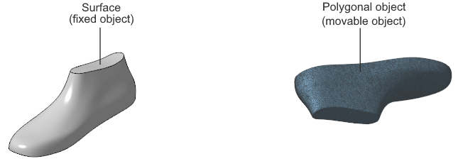
Appearance and initial position of the objects to be combined
Combining with the initial alignment disabled gives an unsatisfactory result. When viewing, it is evident that the phantom of the polygonal object (shown in pink) is rotated relative to the model surface and is located far from it (Fig.The process of alignment, a).
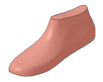
Let's choose the alignment method According to inertial characteristics. Viewing the result shows the exact alignment of the phantom with the surface (Fig.The process of alignment,b,).
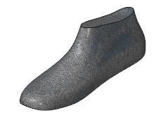
Let's confirm the alignment. The polygonal object has taken the place of the phantom (Fig.The process of alignment,c) The result of the combination satisfies the requirements.
|
|
|
a) |
b) |
c) |
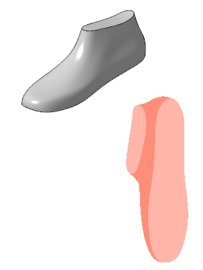
The process of alignment:
a) viewing the result of the alignment performed without alignment,
b) viewing the result of the alignment performed with alignment according to inertial characteristics,
c) the result of alignment objects with alignment according to inertial characteristics
Alignment method By three points consists of combining points indicated on the surfaces of objects
This method gives a good result for any mutual arrangement of objects. In addition, it allows you to accurately combine objects, even if they only partially match in shape (for example, if a polygonal object repeats not the entire surface of the product, but only part of it).
After choosing the method By three points a table of points appears on the Parameter panel objects.
Specify three points on the surface of the stationary object and three points on the surface of the object that will move. For good alignment, the specified points must be located on identical areas of the objects' surfaces.
The specified points are shown in the graphic area and entered into the Parameter panel table. If necessary, you can delete the points and specify them again.
Example
As a result of scanning the product Frame managed to obtain a polygonal object that repeats not the entire surface of the product, but a small part of it. It is necessary to combine the existing polygonal object with the body built in the original model of the product.
The objects being combined do not have symmetry. The shape of the polygonal object only partially repeats the shape of the original model.
The objects are located far from each other. The polygonal object is rotated relative to the body in the model.
|
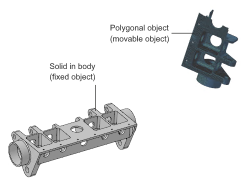
Appearance and initial position of the objects to be combined
By default, objects are aligned with the initial alignment by inertial characteristics. When viewing the result, it is clear that the phantom of the polygonal object is shifted relative to the model body (the phantom is displayed in pink). This position is due to the alignment of the centers of mass of the objects.
|
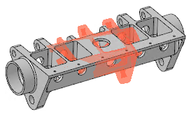
Combination with preliminary alignment according to inertial characteristics
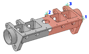
For more accurate alignment, we will choose the method Alignment by three points and indicate the points on the objects to be combined.
|

Specifying points on combined objects
When viewing the result, it is clear that the corresponding points have aligned, and the phantom of the polygonal object has taken the desired position relative to the body of the model (Fig.The process of alignment, a).
Let's confirm the alignment. The polygonal object has taken the place of the phantom (Fig.The process of alignment, b) The result of the combination satisfies the requirements.
|
|
a) |
b) |
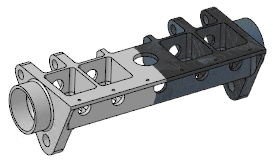
The process of alignment:
a) preview of the result of the alignment,
b) the result of alignment
Alignment in arrow direction and point
Alignment method In arrow direction and point includes two stages: initially, the moving object is positioned similarly to the stationary one, and then the specified points of the objects are combined.
This method gives a good result for any mutual position of objects. It allows you to accurately combine both similar objects and objects that partially match in shape (for example, if a polygonal object does not repeat the entire surface of the product, but only a part of it).
After choosing the method In arrow direction and point the table of object points appears on the Parameter panel. The window Moved object is also displayed on the screen. It displays the polygonal object selected for aligning (the moving object). This object is hidden in the graphic area. The second aligning object (the stationary object) remains in the graphic area.
1.In the window Moved object rotate the moving object so that it is positioned similarly to the stationary object. Rotation is performed using keyboard shortcuts or with the mouse.
2.Specify a point on the surface of a unmoved object and a point on the surface of an object that will move. The positions of the points must be similar.
The specified points are shown in the graphic area and entered into the Parameter panel table. If necessary, you can delete the points and specify them again.
Example
It is necessary to combine a polygonal object obtained by scanning a product Propeller, with the body built in the original model of this product.
The objects being combined have similar shapes. The polygonal object is located at some distance from the body and is rotated relative to it.
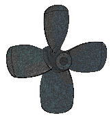
|
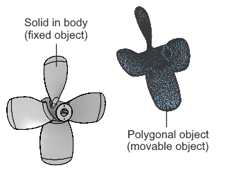
Appearance and initial position of the objects to be combined
The alignment with the initial alignment disabled does not satisfy the requirements. When viewing the result, it is clear that the polygonal object phantom (shown in pink) is shifted and rotated relative to the body (Fig.Options for combining objects, a).
Combination with alignment by inertial characteristics gives a better result, but it is insufficient for further verification of deviations (Fig.Options for combining objects, b).
|
|
a) |
b) |
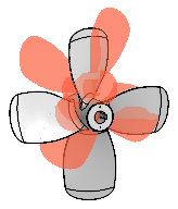
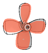
Options for combining objects:
a) alignment without initial alignment,
b) combination with alignment according to inertial characteristics
For more precise alignment, we will select an alignment method In arrow direction and point. An additional model window appears on the screen, into which the moved object is transferred.
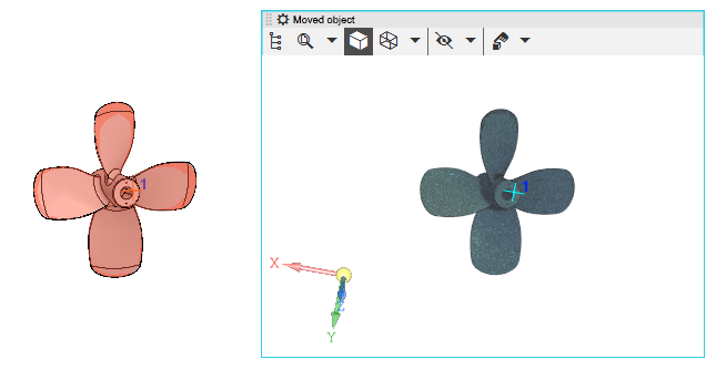
|
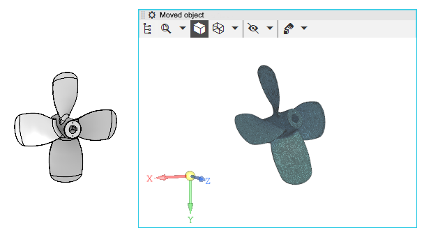
Display of alignable objects when selecting alignment by view direction and point
For the convenience of further work, let's increase the scale of displaying objects.
Let's rotate the polygonal object so that its position becomes identical to the position of the body in the model (rotation is performed with the mouse in the window Moved object). Then we specify a point on the surface of the polygonal object and a similar point on the surface of the body.
|
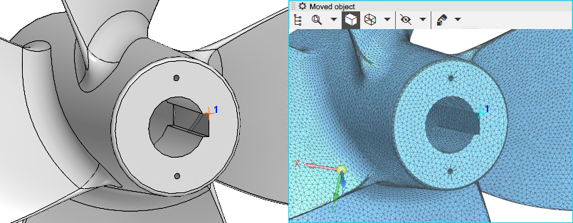
The result of rotating a polygonal object and specifying points
Let's move on to viewing the result — the phantom of the polygonal object has taken the required position relative to the body of the model (Fig.The process of alignment, a).
Let's confirm the combination of objects. The polygonal object has taken the place of the phantom (fig.The process of alignment,b). The result of the alignment satisfies the requirements.
|
|
a) |
b) |
The process of alignment:
a) preview of the result of the alignment,
b) the result of alignment