|
Performing alignment |
Scroll |
Aligning a polygonal object with a model object: general information
The command used to perform the alignment is Match  .
.

Procedure
1.Select a model object—a body, surface, or polygonal object—with which you want to merge the polygonal object being checked. To do this, select the desired object in the graphic area or in the Model Tree. The selected object is highlighted, and its name is displayed in the field Unmoved object.
2.Select the polygon object to be merged. To do this, select the desired object in the graphic area or in the Model Tree. The selected object is highlighted, and its name is displayed in the field Moved object.
3.By default, object alignment is performed over 10 iterations. This value is considered sufficient to achieve good alignment quality.
If the alignment result is unsatisfactory and changing other alignment parameters does not produce the desired result, change the value in the Number of iterations field. This may improve alignment accuracy, but the process will take longer.
4.By default, the Points selection option is enabled in the Parameter Panel. This means that the system automatically selects the most suitable points for alignment. Using this selection speeds up the alignment process and produces good results in most cases. In particular, this allows for better alignment of objects that partially overlap or do not fully match in shape, for example, if only a section of the surface was scanned for comparison rather than the entire surface.
If you are unable to achieve a good result during the alignment process, disable the Points selection option.
5.Depending on the shape and position of the objects, determine whether the polygonal object needs to be aligned with the model object beforehand.
|
Pre-alignment allows you to first «roughly» align the objects and then apply the main alignment algorithm to them—the iterative nearest-neighbor algorithm, in which the point cloud of the moving object is aligned with that of the stationary object. |

The alignment method is selected from the Initial alignment list. The available options are shown in the table.
Initial alignment options
|
Variant |
Description |
|
Usage |
|
Do not perform |
Alignment is not performed. |
Used for objects with similar elements. These elements, as well as the objects themselves, must be located close to one another. |
|
|
According to inertial characteristics |
The principal axes of inertia of the objects and their centers of mass are aligned. This is done automatically. |
Used for objects of similar shape that are not symmetrical and are spaced apart from one another. |
|
|
By three points |
The specified points on the objects are aligned. Additional user action is required. |
It can be used for objects of any shape and orientation. |
|
|
In arrow direction and point |
Initially, the moving object is positioned in the same way as the stationary object, and then the specified points on the objects are aligned. Additional user action is required. |
It can be used for objects of any shape and orientation. |
The specifics of using preliminary alignment in different models, as well as setting parameters for the selected method, are described in Initial alignment section.
6.To see how the objects will be positioned after alignment using the specified settings, click the button View result . The button becomes available after you specify the objects to be aligned and the initial alignment parameters for the selected method.
After clicking the button, the polygonal object being moved will disappear, and its phantom will appear in the new position in the graphics area (see the figure below).
If the alignment takes some time, a progress indicator appears in the graphics area. You can stop the process by clicking the Cancel button on the progress bar.
7.Visually evaluate the alignment result. Pay attention to areas of the model object’s surface that do not align with the polygonal phantom; to the intersection lines between the object’s surface and the phantom; and to protruding areas of the object’s or phantom’s surface.
If the result does not meet your expectations, change the method and/or parameters of the initial alignment; for example, specify different points for the By three points method. You can also change the number of iterations or disable point sampling. After changing the parameters, click the View result button again. The phantom of the object being moved will assume a new position.
The figure shows the result for two alignment options of the same objects. The phantom of the polygonal object is pink.
|
|
a) |
b) |
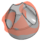
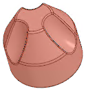
Evaluation of the result of the match:
a) inaccurate alignment (the phantom of the polygonal object is rotated relative to the body of the model),
b) precise alignment (the phantom of the polygonal object coincides with the body of the model)
8.When the required position of the object is reached, confirm the alignment by pressing the button Create object  .
.
The polygonal object will move to the set position
9.To complete the command, click the button Finish .
.
The objects are ready for performing Deviation analysis.
|
If the deviations obtained during the analysis exceed the expected values, you can run the object match process again and move the polygonal object relative to the position it occupied as a result of the previous alignment. You can also undo the alignment and re-align the objects. |

