|
Slope from baseline |
Scroll |
Slope from baseline: general information
Slope from baseline: general information
The slope from the baseline is executed using the Slope from baseline  command.

Step-by-step instructions
1.Set the slope direction. Therefore, indicate straight-line, plane object or revolution surface (excluding sphere) in the graphic area of the model or in the Design Tree. A straight-line object sets the direction parallel to itself, a flat object sets it perpendicular to its plane, and a revolution surface – parallel to its axis. The object name is displayed in the Basic direction field.
You can set the slope direction using a vector. To build a vector, click Design Vector button  to the right of the Basic direction field. Vector vector construction. Follow the plotting process and press the Create Object button. The system will return to the slope construction process, the created vector will be automatically selected as the guiding object.
2.Define a baseline—the starting edge of the face to be skewed. To do this, select an edge or a chain of edges in the graphics area.
A single selection can include either a single specified edge or a group of edges that meet a specific condition. Use the Quick Access Toolbar to set the condition.
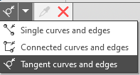
The names of the selected objects are displayed in the Baseline field.
1.If necessary, specify the slope side. By default, the slope side is selected automatically by the system. The side name is displayed in the Side field. To specify the slope side, you can select any of the faces adjacent to the baseline.
2.Specify the slope angle or select its value from the drop-down list in the Angle field. Negative values are allowed. The slope angle is measured from the projection of the object defining the baseline onto the cross-sectional plane of the slope surface.
You can reverse the slope direction using the Reverse Direction button  to the right of the field Corner.
3.If you want to rebuild the fillets at the edges of the sloped faces as if they had been created after the slope was generated, enable the Adapt fillets option. Note: If there are fillets whose edges fall within the slope baseline, those fillets will not be adapted.
4.If necessary, specify the slope name in the Properties section.
5.To complete the operation, click the Create Object button  .
.
After confirming the operation, a deviation from the baseline appears in the model, and a corresponding icon appears in the Construction Tree .
6.To complete operation of the command, click Finish  .
.
Tips
•The slope angle values and direction can be set in the graphic area using defining points.
•You can use the geometrical calculator.
•You can assign tolerances for operation parameter values expressed as angular values. To do this, you should call the Tolerance command located in the menu of the required parameter, or click the  icon displayed in the parameter field (the icon is displayed if a tolerance is assigned to the parameter value). More details on assigning tolerance...
See Also
