|
Splitting |
Scroll |
Use the Surface Split command  to split a surface.

Step-by-step instructions
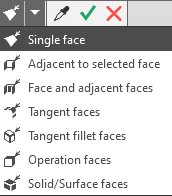
1.Set the split surface. To do this, specify a face or several faces of the same body/surface in the graphic area. For one indication, you can select one face or a group of faces that satisfy a certain condition. The elements of the Quick Access Toolbar are used to set the condition.
|
If you want to split all the faces of a body or surface, then you can specify not the faces, but the entire body/surface. In this case, the name of the selected body/surface will appear in the Surface Faces field. More about features of solid/surface selection... |

The selected faces are highlighted, and their names are displayed in the Surface Faces field on the Paameters Panel.
2.Specify a secant object or set of objects. To do this, activate the Secant Object field and specify the desired objects in the graphical area or in the Model Design Tree. The following are used as secant objects:
•coordinate plane or construction plane,
•a face of a solid or a surface
•solids or surfaces,
•curves lying on the surface
•sketch.
The specifics of specifying split objects depending on their types, as well as the result of the operation for each type, are given in the section. Requirements for sectioning object and its effect on the result of splitting.
If you need to split a surface by the isoperimetric curve, you can plot this curve without exiting the splitting process. To do so, click Design Isoparm Curve  to the right of the Sectioning object field. More about isoparametric curve usage...
The specified secant objects are highlighted, and their names are displayed in the Secant Object field on the Parameters Panel.
The graphical area shows the edge phantoms that are formed when partitioning.
3.If you have selected a sketch as the sectioning object, please select the movement direction of the sketch to form the sectioning surface. To do that, press the corresponding button in the Projection Direction group:
 Both Directions,
 Forward direction,
 Reverse direction.
If you've selected the movement of the sketch in forward or reverse direction, this direction is indicated using an arrow on the phantom in the graphic area.
|
All the contours of the selected sketch are participating in the splitting. You cannot use only selected contours. |

4.You can rename the split operation in the Properties section.
5.To complete the operation, click Create object  .
.
The selected faces are split into several faces, and the icon of the surface splitting operation appears in the Design tree.
6.To complete operation of the command, click Finish  .
.
See Also
