|
Requirements to cutting objects |
Scroll |
Cutting objects must unambiguously define the cutting line, i.e., they must completely intersect the surface being split.
In the case of a polyhedral surface to be split, the split line is also considered fully defined if the cutting object does not intersect the entire surface but rather one or more of its faces, provided that the endpoints of the intersection line lie on the edges of those faces. In this case, only these faces will be split as a result of the operation.
Objects of various types can be selected as cutting objects. The specifics of selecting cutting objects and the resulting division outcomes are described below.
Coordinate plane or auxiliary plane
Any set of planes can be used for the subdivision.
The split occurs along the line where the plane intersects the surface being split.
Edge of a body/surface
You can use one or more faces for the subdivision.
The split occurs along the line where the edges intersect with the surface being split.
In a single selection, you can choose one or more faces that meet a specific condition. To specify the condition, use the elements in the Quick Access Toolbar.
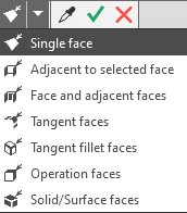
Selecting Faces Based on Conditions
Once the condition has been set, specify the desired face.
Surface or body
Any set of surfaces and solids can be used for the division.
The split occurs along the line of intersection between the surface being split and all faces of the intersecting solid/surface.
If new faces appear on the solid/surface during further editing, the split line will change (provided that the operations modifying the solid/surface are located higher in the tree than the trim operation).
If a solid or surface is selected, the Cutting Object field displays the name of that solid or surface, rather than a list of its faces.
Features of specifying a solid/surface
Curves lying on a trimmed surface
Any set of curves may be used.
Curves may intersect, but must not intersect themselves.
The division is performed along the selected curves.
A single click in the graphics area can select one curve or a group of curves that satisfy a specific condition. The Quick Access Toolbar is used to specify the condition.
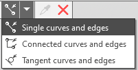
More information on selecting curves based on conditions...
Once the condition has been set, specify the desired curves.
|
There are some specific considerations when using curves with subordinate curve objects (projection curves, intersection curves, etc.). Learn more... |

An isoparametric curve can be used as the intersecting object.
If the curve has already been created in the model, select it as usual.
If there is no curve in the model, create one without leaving the splitting process. To do this, click the Isoparametric curve button to the right of the Cutting object field. This will start the operation to create an isoparametric curve on the surface.
If the surface being split consists of a single face, it is selected automatically; if it consists of multiple faces, you must specify the face on which the curve should be located. After the curve is constructed, the system returns to the splitting operation. The created curve appears in the Construction Tree and is automatically selected as the intersecting object.
|
If the Cutting Object field contains previously selected curves, the isoparametric curve will be added to the list of curves that make up the secant object. If the objects in the field are not curves, the isoparametric curve cannot be added to the secant object. The curve is constructed in the model but is not selected as a secant object. |
Sketch
Only one sketch may be used.
The sketch objects may consist of any number of closed and/or open contours. The contours may intersect, but must not have self-intersections.
The split occurs along the line of intersection between the surface being split and the surface obtained by extruding the sketch perpendicular to its plane.
