|
Intersection of model objects with the sketch plane |
Scroll |
In a sketch, you can create curves and/or points that represent the intersections of selected model objects with the sketch plane. To create intersections, use the Intersection Objects command  .
.

Procedure
1.In the graphics area or in the Design Tree, select the model object(s) to intersect with the current sketch plane.
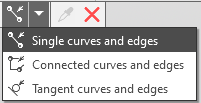
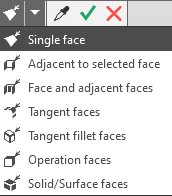
The object name is displayed in the Objects field of the Parameter Panel.
•If an intersection is found, its phantom is displayed in the graphics area on the sketch plane. These can be points, curves, or lines—depending on the specified model object. More about intersections of the sketch plane with objects of different types...
•If no intersection is found, or if it is not found for all specified objects, a corresponding message appears on the screen.
 A parametric constraint—Projection Constraint—is automatically applied to the intersection object.
 If the intersection results in a closed intersection curve, Endpoint Projection constraints are also applied to it. The parametric constraints of intersection curves are similar to the constraints of curves formed when projecting model objects onto a sketch; see the section Parametric Constraints of Projection onto a Sketch.
2.If necessary, create an intersection with an extension of the specified object. To do this, enable the Extend to Intersection option. This option allows you to construct an intersection with an extension of a straight line, a circular arc, or an elliptical arc.
3.You can change the style of the lines and points that appear at intersections in the Line Style and Point Style fields on the Parameters Panel.
4.To create an intersection, click the Create Object  button.
If an object intersects a sketch plane at a point, an intersection point object is created in the sketch; if it intersects along a line, an intersection curve or an auxiliary line is created. The properties of the intersection curve are similar to those of a curve obtained by projecting model objects onto the sketch. Just like a projection curve, an intersection curve can be trimmed, extended, etc.; see the section "Features of Working with Projection Curves."
|
•An intersection with an object tangent to the sketch plane is created when the tangency occurs along a line, but not when it occurs at a point. •An intersection with an object that belongs entirely to the sketch plane is not created. |

Intersection of the sketch plane with objects of different types
When the sketch plane intersects with model objects, various geometric objects are created; see the table.
Results of the intersection of the sketch plane with model objects
Model object |
Intersection result |
|
Face of a solid or surface |
Set of curves |
|
Edge of a solid or surface, spatial curve, sketch curve |
Set of points |
|
Coordinate or auxiliary axis |
Point |
|
Coordinate or auxiliary plane |
Line |
|
Solid, surface |
Set of curves |
|
Sketch |
Set of points |
If the object is a sketch or a multi-segment curve (such as a contour or a polyline), keep the following points in mind.
To intersect with the sketch plane, you can select either the entire object by specifying it in the Tree, or a part of the object (a single line in the sketch or one of the curve segments) by specifying it in the graphics area. The result of the sketch reconstruction after changing the plane’s position depends on how the object is used:
•If a portion of the object was used, the new position of the point is determined as the intersection with that same portion or—in the case of a line segment or arc—with its extension; see Figure a). If there is no intersection, the sketch containing the points is marked as incorrect.
•If the object was used in its entirety, it is interpreted as a chain of curves (in the case of a sketch, there may be multiple chains). Therefore, the new position of the point is determined as the intersection with the same chain; see figure b). As a result, the point may move to another link in the chain. No extensions of the links are created. If there is no intersection, the sketch containing the points is marked as an error.
|
|
a) |
b) |
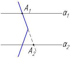
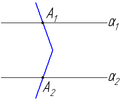
The initial (A1) and new (A2) positions of the point of intersection of the sketch plane
and a contour consisting of two line segments, when the sketch plane is shifted downward (its positions are denoted by α1 and α2 ):
a) if one of the line segments forming the contour is selected for the intersection,
b) if the entire contour is selected for the intersection
Similarly (but without extending the objects), the intersection result is determined in cases where a solid or surface, or individual faces of a solid or surface, are selected:
•When a body/surface is selected in its entirety—by specifying the body/surface itself, if the Tree is in structure view, or any of the operations that make up the body/surface, if the Tree is in construction history view— — then the intersection is determined immediately with all the faces forming the body/surface. Subsequently, if new faces intersecting the sketch plane are created during modification of the body/surface, the intersection lines change accordingly. If, however, the faces intersecting the sketch plane disappear, or if the solid/surface ceases to intersect the sketch plane, it is marked as an error.
•When individual faces of a solid or surface are selected—by pointing within the graphics area—the intersection is determined for each face. Subsequently, if the shape or position of the faces changes, their lines of intersection with the sketch plane also change. If at least one of the selected faces disappears as a result of modifying the solid or surface, or ceases to intersect with the sketch plane, the sketch is marked as invalid.
|
Operations that modify the body affect the sketch if they are located higher in the model hierarchy than the sketch. Otherwise, the sketch remains unchanged. |
See also
