|
Methods for determining extrusion depth |
Scroll |
 At Distance
Extrusion depth is set in the field Distance. Its value can be both positive and negative. The negative depth is measured in the opposite direction to the positive.
|
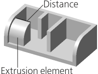
Extrusion to distance
|
When this method is selected in the Main section of the Parameter Panel, symmetrical building is available on both sides of the section. To do this, set the Symmetrically toggle switch in position I (enabled). In this case, in the Distance field enter the total value of the extrusion depth. |

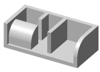
 Through all
The extrusion depth is determined automatically.
The element is extruded to the minimum distance at which all points of the end face are behind the bounding box of the model (or in the plane of the face of the parallelepiped if extrusion is perpendicular to this face).
|

Extrusion Through All
When constructing a dimensional parallelepiped, only solids are taken into account, therefore, if there are no solids in the model, the method of determining the depth Through all not available.
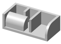
 To object
Extrusion depth is automatically determined by the position of the user-specified object – a vertex or surface (face, plane).
|
|
a) |
b) |


Extruding an element
a) to vertex; b) to face
•When selecting a vertex, the extrusion depth is calculated so that the end of the element takes the position closest to the specified vertex.
•If a face, a sketch, a contour built along sketch lines or edge edges is used as a section, then an extrusion depth is calculated at which the surface of the element face (or its continuation) passes through the specified vertex,
•If an edge, a spatial curve or an arbitrary contour is used as a section, then the extrusion depth is determined as follows. A straight line is constructed through the specified vertex in the direction of extrusion. On this line is the point nearest to the section. The depth of extrusion is taken to be equal to the distance from this point to the specified vertex.
•When choosing a surface, the element is extruded to this surface (or its extension). The end of the element has the shape of the selected surface.
To specify an object that defines the extrusion depth, click in the Object field and specify a point object, face or plane in the graphics area (the point can also be specified in the Design Tree). The name of the specified object is displayed in the Object field.
Below the Object field there is a field Move. A zero value in this field means that the element is extruded exactly to the specified object. In this case, the end of the obtained element passes through the vertex or coincides with the specified surface.
If you want the extruded element to "go in" for the specified object or "did not reach" it, enter Move positive value. It can be put off both in the direction of extrusion (in this case the element will be extruded "for" the object for the specified distance), and against the direction of extrusion (in this case the element will not reach the object for the specified distance). The direction of counting is set using the To object  /For object
  button to the right of the Move field.
|
If the object determining the extrusion depth is a surface, then at a given distance from it an equidistant surface is built, to which the extrusion is made. |
|
|
|
a) |
b) |
c) |
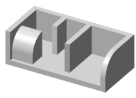
Extruding an element
a) exactly to vertex; b) over vertex; c) without reaching vertex
If the element is extruded to the vertex, then on the Parameter Panel there is an option Cut off . It allows you to cut off the extrusion element by a plane passing through the specified vertex perpendicular to the extrusion direction. In this case, the element has a planar end, regardless of the shape of the section.
|
Extension of faces and surfaces of complex shape is not always possible. In this regard, pay attention to the following features. •When extruding to the vertex – if the specified vertex does not lie on the end of the received element, then in some cases the construction can be performed only when the option is on Cut off. •When extruding to the surface — if the contours of the obtained element end are beyond the specified surface, building will only be performed correctly if this surface can be extended. |

The extrusion depth is determined automatically.
The element is extruded in the extrusion direction to the nearest face or connected set of faces which fully overlap the section. The operation applies to faces of solids contained within the operation application area. The butt of the resulting element is shaped as a face or faces to which the extrusion is performed.
This building method is convenient, for example, for extruding an element to a stepped surface formed by multiple faces, see the figure.
|

Extruding an element using the To Nearest Surface method
In case of cutting, search of intersections of the created element with a solid located in the building direction is performed, and the volume obtained by intersection is cut from this solid. If multiple faces of the solid are located in the building direction, only the volume limited by the face or connected set of faces nearest to the section will be cut. If the application area comprises multiple solids, the search of intersections and cutting is performed for each solid.
The figure shows building holes in a solid by cutting To nearest surface. A sketch located on the face of this solid is selected as a section.
|
|
a) |
b) |


Cutting an element using the To Nearest Surface method
(the section sketch is on the solid face):
a) phantom element; b) building result
Features of extrusion to the Nearest Surface
•The operation can be executed if the model has at least one solid/surface/component. If none of these objects exists, the element will not be created.
•If the nearest faces located in the extrusion direction do not fully overlap the section, then the element is extruded to the face of the bounding box of the solid/surface/component which these faces belong to.
•If no faces of solids are located in the extrusion direction, then the element is extruded to the face of the model bounding box built with account of all the solids, surfaces and components it contains.
•If the section is a sketch with multiple contours, then building is only performed for those contours that are fully or partially overlapped by the nearest faces belonging to the same solid.
•If multiple objects are selected as section, each of them is extruded to the corresponding face(s), i. e. to the face(s) fully overlapping this object. If no such face(s) exists, extrusion of this object is performed to the face of the model bounding box.
|
To build an extrusion element correctly, the section and the extrusion direction should be selected in the way that the nearest faces to which the element is built are entirely overlapped by objects selected as sections. |
Features of cutting to the Nearest Surface
•This operation cannot be executed in the following cases:
•no solid created in a model or included in a component exists in the building direction,
•the volume cut out of the solid is equal to this solid.
•If the section is a sketch with multiple contours or several regions of the same sketch, the building is only performed for those contours/regions that create elements intersecting with the solids in the application area. Resulting elements can either intersect with one solid or with various solids.
•If a solid included in a component exists in the cutting direction, the element is cut from this solid. The cutting operation is located in the Design Tree in the Components section.