|
Cut Line |
Scroll |
In KOMPAS-3D, a section line of the following types can be created:
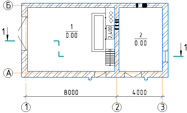
Creation of lines of cut for civil engineering in general is similar to creation of lines of cut for mechanical engineering.
The differences are as follows:
•Instead of letters in designation, numbers are used;
•Generation of a new view after creation of a line of cut is controlled by the Create view option.
If the option is enabled, then after creation of a cut line automatic start the Command to create a new view. As a result of execution of this command, in the drawing there will appear a view whose caption will be associatively linked to the created line of cut. Automatic Adding a hyperlink to the section linefor the switch to the view.
|
Into the name of view linked to the line of cut, the word "Cut" is added by default. It can be deleted or replaced in the Dialog for setting up parameters of section line. |

For precise positioning of the cursor, you can use Snaps and geometrical calculator.
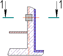
To create a line of simple cut, the Cut Line  command is used.

Step-by-step instructions
1.Set the initial and final points of the line of cut. In the graphic region, a designation phantom will appear.
You can set the direction of the line of cut. To that end, before indication of the final point select a straight-line object. On aiming the cursor at the object, the object will be highlighted, and the cursor will take the shape of square "trap".
After the indication of the guiding object, its name will appear in the Object field on the Parameter Panel. Depending on the direction of movement of the cursor on indication of the final point, the line of a cut will be parallel or perpendicular to the selected object.
2.In the Text field and on the phantom of designation, the number of line of cut suggested by the system is displayed. If necessary, change the caption and/or its typeface. Details...
3.Indicate, near which of the arrows the additional text (if any) should be placed. To that end, press the required button in the Additional text group:
 At First Arrow,
 At Second Arrow.
4.If after labeling a line of cut the view associated with it, include the option Create view.
5.Select the look and feel of the arrow from the Arrow drop-down list.
|
The list of arrows available for selection, as well as the sequence of arrows in the list is determined by the setting of the filter done in the Symbols for civil engineering – Cut Line – Arrow filter section in the dialog for setting up the current document. |
6.Click from that side from the line of cut where arrows should be placed.
After setting the position of arrows, building the line of cut ends automatically.
|
Cut Line
To create a line of complex cut, the Complex Cut Line  command is used.
Step-by-step instructions
1.Indicate the vertices of the line of cut.
After indication of the first two vertices, a phantom of the line will appear in the graphic area.
You can set the the direction of segments of the line of cut. To that end, prior to indication of the final point of segment select a straight-line object. On aiming the cursor at the object, the object will be highlighted, and the cursor will take the shape of square "trap".
After indication of the object, its name will appear in the Object field on the Parameter Panel. Depending on the direction of the cursor movement, the indication of the final point the segment of the line of cut will be placed in parallel or perpendicularly to the selected object.
After indication of the final point of segment, the Object field will be cleared.
To make segments perpendicular to one another, enable the orthogonal drawing.
2.If it is required to reconfigure the line of cut (to change position of vertices, to delete vertices, to create kinks on built segments), switch to the Edit mode. That is done the same was as on creation of a line of complex cut for mechanical engineering. Details...
To continue building a line of cut, return to the Creation mode.
3.In the Text field and on the phantom of designation, the number of line of cut suggested by the system is displayed. If necessary, change the caption and/or its typeface. That is possible only in the editing mode. Details...
4.Indicate, near which of the arrows the additional text (if any) should be placed. To that end, press the required button in the Additional text group:
At First Arrow,
At Second Arrow.
5.If after labeling a line of cut associated view, include the option Create View.
6.Select the look and feel of the arrow from the Arrow drop-down list.
|
The list of arrows available for selection, as well as the sequence of arrows in the list is determined by the setting of the filter done in the Symbols for civil engineering – Cut Line – Arrow filter section in the dialog for setting up the current document. |
7.Indicate, on which side of the line of cut the arrows should be placed. To do this, use Change Direction  button to the right of the Arrows direction element.
8.To complete building a line of cut, press Create object  button.
|
Complex Cut Line