|
Types of face extension |
Scroll |
To select a face extension type, use the corresponding button in the Extension type group and specify the required parameters, see the table.
Extension types
Extension type |
Result of plotting |
|
|
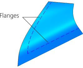
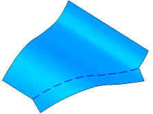
By the same surface A face is extended without adding new faces — beyond the open edges by its theoretical surface. Specify the position of the lateral edges of extension. If the surface to be extended is not analytic (see the add-on Parametric representation of the surface. Isoparametric curves), then building the extension section By the same surface is impossible. In this case, plotting using this method is performed By tangent but without creating new faces. |
|
|
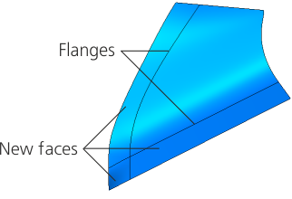
By tangent Extension is made by creating new faces which are tangent to the source faces along the selected edges. Specify the position of the lateral edges of extension. If plotting By tangent resulted in an element which is an extension of the surface being extended, (that is, the plotting result is no different from extension By the same surface), then the new face is merged with the source face. |
|
|
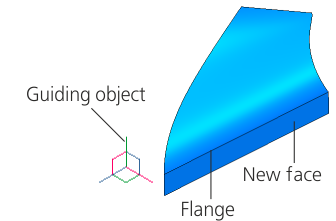
Surface extension is performed by creating new faces formed by moving the selected flanges in the specified direction. Specify the direction of extending the faces. |
|


Position of the lateral edges of the extension
If the Extension Type group of elements specifies the edge extension option By the same surface or By tangent, the Parameter Panel will make available a group of elements Side Edges.
Select the position of lateral edges of extension using the corresponding button:
 As extension of original lateral edges,
 By normal to specified borders.
Possible positions of lateral edges are shown on the picture below. The edge with the face extended beyond it is shown with a dashed line.
|
|
|
a) |
b) |
c) |

Possible position of lateral edges
a) original object, b) extension of initial lateral edges,
c) extension by normal to specified flanges
Direction of extending the faces
If the Extension type group of controls has the By direction method selected, the flanges of the faces are moved in the specified direction.
You can use any straight-line or planar object as a guiding object. Straight–line and flat objects are listed in the table.
•Direction set by a straight–line object is a straight line parallel to the object.
•The direction given by a flat object is a straight line perpendicular to the object.
A vector also can be a guiding object.
Please specify a guiding object in the graphic area or in the Design tree, or plot a vector. The name of the selected object is displayed in the Direction field.
To build a vector, click Build a vector  button to the right of the Direction field. This will start the process of vector construction. Follow the plotting process and click Create Object. The system will go back to the surface extension operation, the new vector will be automatically selected as the guiding object.
The direction of edge extension can be changed to the opposite by pressing Change direction  button to the right of the field Length. This field is available if the Method group of controls has the For specified length setting selected.