|
Dimension Type |
Scroll |
The Type group of buttons defines position of dimension line and extension lines of a dimension. It is available on the Parameter Toolbar when creating/editing the following dimensions:
•linear dimensions (except smart dimensions, dimensions from line to point, dimensions trimmed and arc dimensions),
•angular dimensions (except smart dimensions),
•diameter and radial dimensions.
|
For smart linear and angular dimensions, the position of the dimension and leader lines is defined using the mouse. |

For a description of how to select the type for various dimensions, see below.
The element |
Description |
|
|
Parallel to Object |
The dimension line is parallel to the line going through the dimension snap points (see Fig. a). This button is displayed on the Parameter Toolbar only when setting a simple linear dimension. |
|
Horizontal |
The dimension line is parallel to the OX axis of the current view coordinate system (see Fig. b). |
|
Vertical |
The dimension line is parallel to the OY axis of the current view coordinate system (see Fig. c). |


|
|
|
a) |
b) |
c) |
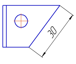
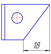
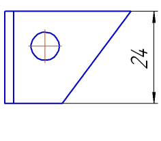
Position of dimension line for linear dimension:
a) parallel to object; b) horizontal; c) vertical
|
When setting simple linear dimension, note the following. •If a circle or an ellipse is selected for dimensioning, dimension type can only be Parallel to Object. Selection of any other type is automatically canceled. •When setting a dimension between two ellipses, a circle and an ellipse/ellipse arc, ellipse arcs, or an ellipse and arc, you need to select the dimension type after you specify the second object. The type selected before or while specifying objects is automatically changed to Parallel to Object. •When labeling the dimension between two circles/arcs (in any combination) with extension lines, tangent to the circles/arcs, the dimension type can only be Parallel to object. Selecting another type is not available: the buttons are gray. |
Type selection buttons become available after setting angle sides.
Item |
Description |
|
|
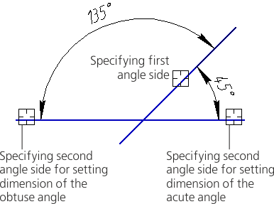
Minimum Angle |
Dimension is set to an acute angle. |
|
Maximum Angle |
Dimension is set to an obtuse angle. |
Depending on which angle (acute or obtuse) is created by setting angle sides, the system will automatically select one of the above types. The figure shows all possible places to set angle sides and the corresponding auto-determined angles. |
||
|
||
|
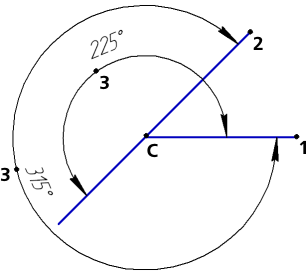
Angle larger than 180 degrees |
Dimension is set to an angle larger than 180°. This option may only be selected manually. Please, note that there are two angles that are larger than 180° between the two sides: •angle that complements the acute angle between the sides to 360°, •angle that complements the obtuse angle between the sides to 360°. To select the required option, specify the point that will determine dimensional line location. |
|


|
When you set groups of angular dimensions with common datum You can only select the type for the first dimension in the group before it is fixed. The type is system-defined for all the other group dimensions. You cannot change it. |
Types of Radial Dimension
The element |
Description |
|
|
Not from center |
Dimension line is not displayed from the circle center. |
|
From center |
Dimension line is displayed from the circle center. |


Types of Diameter Dimension
The element |
Description |
|
|
No Break |
The entire dimension line is displayed. |
|
Trimmed |
The dimension line extends beyond the circle center to a distance equal to 1/5 of the circle radius but not less than the distance specified in this document for the dimension line to extend beyond the text (see section Parameters). |

