|
Geometric Tolerance |
Scroll |
To create a geometric tolerance symbol and placement of surface designation, do the following actions.
1.Invoke the Geometric Tolerance  command.
In the graphic area, a designation phantom will appear.

2.Indicate the object to placing tolerance (part contour, dimension leader, etc.). The name of the selected object will appear in the Object field on the Parameter Panel.
3.On the object, indicate the point to which the tolerance leader line points.
4.Set the point for insertion of a tolerance marquee.
Depending on the direction of the movement of the cursor, during indication of an insertion point there will appear an auxiliary trajectory parallel to the axis of absolute coordinate system or perpendicular to the designated object at the point to which the leader line indicates.
To display all auxiliary trajectories, press and hold the <Ctrl> key. To disable display of auxiliary paths when indicating the point for insertion of designation, press and hold the <Alt> key.
|
For precise setting the position of designation, it is possible to use snaps and geometrical calculator. |

The position of tolerance marquee can also be set without indication of the object being designated – by a click in the free space of the graphic area.
5.After indication of the point of insertion of a tolerance marquee, the Add Text subprocess will be started automatically. Generate a tolerance table.
Upon the end of the Add Text subprocess, the system will return to labeling the designation. The generated caption will appear in the Text field and in the cells of the tolerance table. You can edit the text by clicking inside the Text or in a cell of the tolerance table, as well as by pressing any of the alphanumeric keys on the keyboard.
6.The bottom left corner of the tolerance marquee coincides with the insertion point. If it is required to change the position of a marquee relative to the insertion point, activate the respective point of the Position element.
7.The tolerance marquee is placed horizontally. If it is required to place the marquee vertically, enable the Vertically option.
8.On the phantom of the marquee, eight characteristic points showing possible places of outlet of branches are displayed. Create the required number of branches. Details...
Each new branch is created with an arrow. It is possible to change the arrow type by means of the context menu of defining point at the end of a branch.
9.To complete creation of geometric tolerance designation, press the Create Object button  .
.
10.To complete operation of the command, click Finish button  .
.
You can add a text label.
|
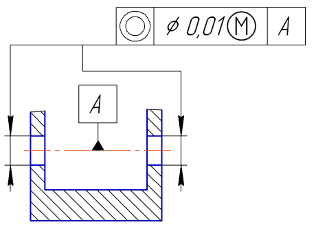
Labeling the tolerance for placement of surfaces