|
Normally with alignment orientation |
Scroll |
This model orientation view is as follows. Initially, the model turns so that the specified flat object becomes parallel to the screen plane, i.e., the view direction coincides with the normal to the specified flat object. Then a guiding object is specified, and the model is rotated around the normal such that the projection of the guiding object onto the specified flat object (or the intersection line of these objects if they are both flat) is positioned either horizontally or vertically.
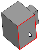
The figures show an example of the model orientation relative to the flat face and the edge of this face as a guiding object (the edge and its projection onto the specified face coincide).
|
|
|
|
a) |
b) |
c) |
d) |

Normally with alignment orientation:
a) specifying a flat face of the model,
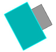
b) the specified face is parallel to the screen,
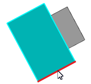
c) specifying of the guiding object,
c) the projection of the guiding object has taken a horizontal position.
To assign the orientation, use the Normally with alignment  command.

Step-by-step instructions
1.Specify the required flat object:
•a flat face,
•a base or auxiliary plane,
•a sketch (it should be specified in the Design tree).
|
It is possible to specify a flat object before invoking the command. |

The name of the selected object will appear in the Normal to... field. The position of the model in the graphic area will change — it will rotate in such a way that the view direction is perpendicular to the specified object. A minimum angle of rotation to the required position is specified automatically.
2.If necessary, you can change the direction of view to the opposite. To do this, click Change direction  button next to the Normal to... field. The model will turn so that the reverse side of the specified flat object is facing the observer.
3.Define how the model rotation will be performed and specify the guiding object.
3.1. To assign the rotation in the group Direction, click one of the following buttons:
 Horizontally (default variant),
 Vertically
In accord with the selected variant, after specifying the guiding object, the model will rotate so that its projection on the previously specified flat object (the intersection line of these objects) occupies a horizontal or vertical position.
3.2. Pick a guiding object in the graphic area or in the Model design tree. A guiding object can be:
•line ( 3D curve, sketch line, edge), whose projection on the specified flat object is a straight line,
•a flat object (plane, flat face, sketch) that intersects with the specified flat object (in the case of specifying a face or a sketch built on the face, the intersection must be within the boundaries of this face).
|
The sketch is specified in the Design tree. |

After pointing to the guiding object, the model will rotate in the required way, and the command automatically finishes working.
See Also