|
Hole Design Methods |
Scroll |
To select a hole construction method, use buttons of the Type group. The following options are available:
•By thickness,
•For Depth,
•To face.
By thickness
The hole, constructed by the method Through thickness  , goes from the specified face (or from the face on which the sketch is built) to the opposite face in a direction perpendicular to these faces. The construction direction is automatically defined; you cannot change it.
If the hole includes a bend or a bend together with the adjoining portions of the sheet part, it passes to that bend and adjoining portions as a "wrapper". In other words, in the sheet part a hole is formed of such shape so that on the flat pattern its contour would precisely match the sketch (when building a cut) or a round hole with the specified radius would be built (when building a hole).
The hole depth can be determined in various ways. To select the required method, use the Determine Thickness list.
•If you need the hole depth to be coincident with the thickness of the sheet part, select a row with the name of the required sheet part.
•If you need to set an arbitrary thickness, select the Specified Value row, then enter a value in the Thickness field.
Building a hole using the By Thickness method is possible under the following conditions:
•using the command Cut in Sheet Solid:
•the sketch should be built on the outer or inner flat face of the sheet element,
•the sketch should intersect the face on which it is built,
•using the command Hole in Sheet Solid:
•an outer or inner flat face of the sheet part should be specified for construction,
•the hole should intersect the specified face.
|
|
|
a) |
b) |
c) |
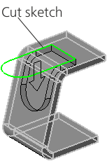
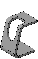
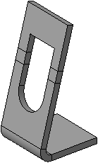
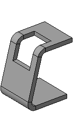
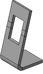
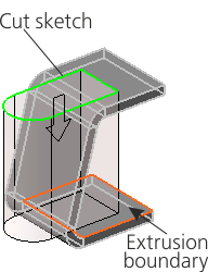
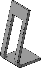
Cut built using By Thickness method
a) construction process, b) construction result, c) result of the changed bend state
For depth, To face
Cutting by the methods For Depth  and To face
  is performed perpendicular to the face on which the cut sketch is built, or to the face specified for construction of a round hole. If the hole includes a bend, it does not pass to that bend as a "wrapper".
The difference between these methods is how the cut direction and depth are set:
•In the method For Depth, the construction direction is automatically defined and you cannot change it. The depth of the hole is set by entering a number in the Depth. You can also specify the hole depth using a defining point or the geometrical calculator.
•In the method To Face, the direction and depth are determined by the selected user object: the cut is made in the direction of this object, and the depth of the cut is equal to the distance from it to the sketch plane of the cut or the face where the round hole is placed. To set an object select a face, surface, base or auxiliary plane in the graphics area (you can also select an auxiliary plane in the Design tree). The name of the specified object is displayed in the Face field.
The following figures demonstrate creation of a cut, which intersects with a bend, using these methods, and the result of unbending this bend.
|
|
|
a) |
b) |
c) |
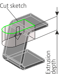
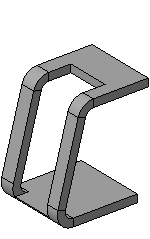
Cut built using the For Depth method
a) construction process, b) construction result, c) result of the changed bend state
|
|
|
a) |
b) |
c) |
Cut built using the To face method
a) construction process, b) construction result, c) result of the changed bend state