|
Controlling the geometry of the component using contextual links |
Scroll |
In this section:
Editing the geometry of a component with the object 'Contextual Link'
Change the geometry of a component using the object Contextual link
Objects"Contextual connection" It can be used to modify the geometry of the component whose construction involved the 'environment'.
By default, the source objects for an operation and/or sketch are the “circles” objects as they were at the moment of creating this operation/sketch. Subsequent changes to the 'surrounding' objects made in the assembly do not affect the result of the operation/constructed sketch.
If it is required that the initial objects of the operation/sketch have geometry considering subsequent changes in the assembly, you need to move the object Contextual Link down the Assembly Feature Tree and place it after the operations that need to be considered. If the geometry of the source objects must correspond to one of the previous construction stages, you need to move the Contextual Link object up the Tree and place it above the operations that should not be considered.
Thus, by changing the position of the object Contextual link in the Assembly Tree, it is possible to modify the geometry of the initial objects of the operation and, correspondingly, the result of this operation.
Step-by-step instructions
1.To change the position of the object Contextual Link in the Design Tree of the assembly, move the mouse pointer over the object's row, click the left mouse button, and when the cursor takes the shape of a four-side arrow  , without releasing the button, move the mouse. In areas of the Design Tree where object placement is possible, a light green bar appears. When the required position is reached, release the button. The object Contextual link has moved to the specified location, but the geometry of the objects in the graphic range will remain the same. If you want to change it , rebuild the model.
2.Rebuild the model.
The result of the operation associated with object Contextual associativity will be changed. These changes will be displayed in the graphic area of the model.
|
Displacement of object Contextual link is advised to be performed when the Design Tree is displayed. Model Design History This option allows to see the sequence of operations execution in the assembly. |

|
For constructing the geometry of a component when editing 'in place', objects of another component can be used. If these objects are subsequently modified by operations performed in the assembly, then you can control the geometry as described above. If the objects of the "environment" component are changed in the component file itself, then these changes are immediately transferred to the assembly. In this case, changing the geometry of the source objects of an operation and, accordingly, the operation result is not possible. |
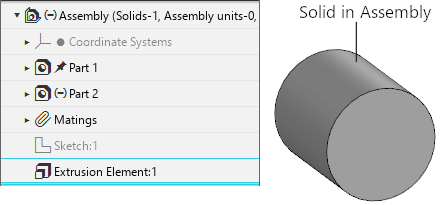
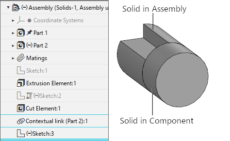
The assembly contains components  Part 1, Part 2 and an extruded solid. In the Design Tree of the assembly, this solid corresponds to the object
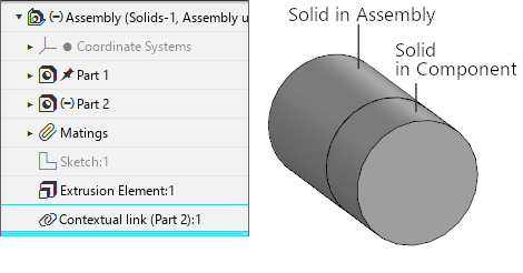
  Extrusion element (Figure 1). When editing 'in place' component Part 2 with the extrusion operation, a new solid was created. Its source object is a face of a solid built in the assembly, therefore, in the Assembly Design Tree, an object
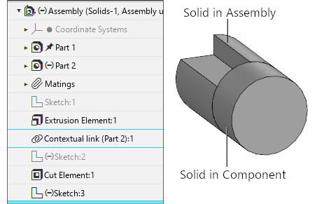
  Contextual Link (Part 2):1 (Figure 2) appeared. When further working with the assembly, the solid built in it has changed — a cut was made in it. Cut operation
  Cut element:1 is located in the Assembly Tree below the object Contextual link (Part 2):1, therefore the geometry of the component has not changed (Figure 3).
|
|
|
Fig. 1 |
Fig. 2 |
Fig. 3 |
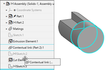
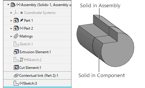
In order for the face of the assembly body to be used for the extrusion element built in the component, taking into account the changes made to it, we will move the object Contextual Link (Part 2):1 (Figure 4) with the mouse and place it after the cutting operation performed in the assembly Cutting Element:1 (Figure 5). Rebuild the model. The geometry of the body in the component has changed (Figure 6).
|
|
|
Fig. 4 |
Fig. 5 |
Fig. 6 |
If it is required to fix the geometry of the source operation/sketch objects in the current view, exclude the Context Link object from the calculation. Further changes in the assembly will not affect the operation result (constructed sketch).
In case of deleting object Contextual connection, the geometry is also fixed, however, if the operation/sketch will be edited later, a new object Contextual connection will appear in the Assembly Feature Tree. It is placed at the end of the Tree, so the result of the operation will be modified considering all the changes made in the assembly.