|
Section of an extrusion element |
Scroll |
In this section:
Possibility of building a solid and thin-walled element depending on the section objects
Procedure for setting the section of an extrusion element
Notes on using sketches and sketch areas as section
Example of using multiple sketch areas as section
You can select one or several objects of a model as a section of an extrusion element. These objects can be:
•sketch or enclosed area in a sketch (see sections Notes on using sketches and areas in the sketch as a section. Using sketches in operations),
•a face,
•3D curve,
•edge.
The set of selected objects may be arbitrary.
|
Utilization of curves with subordinate curve objects (projection curve, intersection curve, etc.) has specific features. Details... |

If required, without interrupting the command you can build a contour or a sketch and add it to the set of section objects.
|
The existing objects (except for sketch areas) can be specified before starting the operation. They will be automatically selected as sections. Specifying sketch areas is only available after the operation is started. |

Objects selected as a section can be located in various planes, but extrusion in the required direction should be available for each of them. If at least one object cannot be extruded in the specified direction, the extrusion element will not be built.
Possibility of building a solid and thin-walled element depending on the section objects
You can select various objects as a section of the extrusion element.
The type and parameters of the selected objects determine the possibility of building the element – solid or thin-walled. More details on thin-walled element...
For some objects, both options are available; when others are selected, only a thin-walled element can be built. Examples of building solid and thin-walled elements are provided on figures.
•The extrusion element can be either solid or thin-walled if the following objects are selected as sections:
•Flat closed object:
•face,
•edge,
•spatial curve,
•contour, regardless of its type,
•sketch containing closed object chains,
•sketch area.
•Non-flat face.
•A closed contour on a non-flat face (type of contour – Contour on face).
•The extrusion element can only be thin-walled if the following objects are selected as the section:
•Flat open object:
•spatial curve,
•contour, regardless of type,
•sketch containing at least one open chain of objects.
•Open or closed non-flat object:
•edge,
•3D curve,
•contour of Arbitrary contour type.
|
If an object for which a solid element cannot be built is selected as section, then building a thin-walled element is automatically enabled in the extrusion operation – the Thin-walled element toggle switch moves to the I (enabled) position, see the section. Thin-walled element. If the 0 (disabled) position of the toggle switch is restored, a solid element cannot be created. In this case, completion of the operation becomes impossible. To create a solid element, this building option should be available for all the objects selected as sections. Otherwise, the element can only be thin-walled. |
Setting the section of an extrusion element
To select the extrusion element section, use elements of the Main section of the Parameter Toolbar. You can select objects already in the model or create new ones.
•To select existing objects as sections, click in the Section field and specify the required objects in the Design Tree or in the graphic area of the model. Objects will be added to the Section in the specified order.
Selecting a sketch and a sketch area has specifics.
When selecting a curve, edge, or face in the graphics area, you can choose a single object or a group of objects that meet a specific condition. To specify a condition, use the elements in the Quick Access Toolbar.

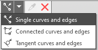
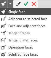
The selected objects are added to the Section field in the order in which they were specified.
•To create a new object (a path or a sketch), follow these steps.
•To draw a contour, click the Draw Contour button  to the right of the Section field. The process of creating the contour will begin. Select the objects to include in the contour, and click the Create Object button.
•To create a sketch, click the Create Sketch button  to the right of the Section field. The sketch placement process will begin, and the system will then switch to sketch mode for constructing the geometry. Perform the necessary steps to construct the geometry, and then exit sketch mode.
Once the contour/sketch creation process is complete, the system returns to the extrusion operation. The created contour/sketch appears in the Construction Tree and is automatically added to the set of cross-sections for the extrusion feature.
The names of all objects selected for the section are displayed in the Section field as a list. You can add objects to the list and remove them from it.
If the cross-section is a sketch (an area within a sketch), you can edit the sketch without interrupting the command. To do this, select it in the Section field and click the Edit button  next to the field. The same procedure applies when editing a contour used as a cross-section.
Notes on using sketches and sketch areas as section
You can select entire sketches or separate areas within a sketch as sections.
•To select the required sketch, specify one of its objects in the graphic area of the model or specify the sketch itself in the Design Tree. In the Section field, the sketch name will be displayed.
•To select an area in the sketch, click inside this area. In the Section field, the name of the sketch and the word Region will be displayed. You can select one or multiple areas within one sketch.
|
Note that areas can only be specified in a sketch that already exists in the model. If a sketch is created when building an extrusion element, the entire sketch is selected. |
A sketch selected as a section may contain one or more contours — closed and open.
When selecting a sketch with multiple closed contours as well as when selecting areas within a sketch, note the following.
•If contours (areas) intersect, the section of the extrusion element is created by merging the intersecting areas.
•If contours (areas) do not intersect, the following building options are possible.
•Element with holes — the section is represented by a non-solid sketch area or a sketch containing contours nested into each other with nesting level 1.
•Element consisting of separate parts — the section is represented by several separate sketch areas or by a sketch containing separate contours or contours nested into each other with nesting level higher than 1.
To learn about the results of building an extrusion element with a section which is a sketch (a sketch area), see section Possibility of building a solid and thin-walled element depending on the section objects.
Example of using areas in a sketch as a cross-section
Construct the model shown in the figure.
|
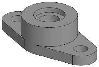
1.Draw a sketch of the model on one of the coordinate planes.
|
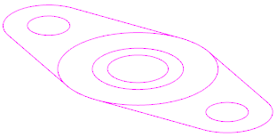
2.Call the Extrusion element  command.
3.By default the operation result is Merging  . Leave it unchanged.
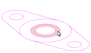
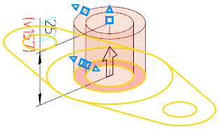
4.Specify a sketch area as a section of the extrusion element. Specify the extrusion method To Distance  and the extrusion depth 25. The figures show the way to specify an area within a sketch and the phantom of the created element.
|
|
5.Press the Create Object button.
|
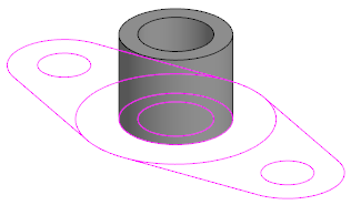
After the extrusion element is created, the command is not completed. The specified parameters — operation result, extrusion method and depth — are saved for subsequent builds.
6.Specify one more sketch area as a section of the next extrusion element and enter the extrusion depth value 30.
|
|
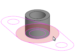
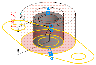
7.Press the Create Object button. The created element will be merged with the previous one.
|
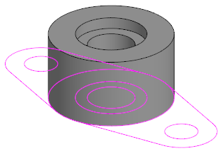
8.Specify the remaining sketch regions as the cross-section of the last extrusion feature.
|
|
Specifying the first region and the element's phantom |
|
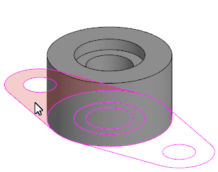
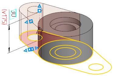
|
|
Specifying the second region and the element's phantom |
|
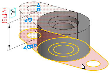
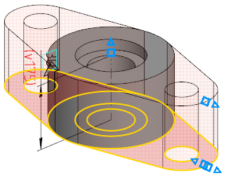
9.Set the extrusion depth to 10.
|
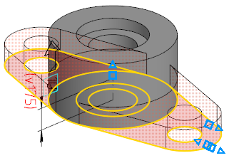
10.Press the Create Object button.
|
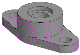
11.If you don't need the sketch for further work, hide it.
