|
Trimming |
Scroll |
The Surface trimming  command is used for surface trimming.
Step-by-step instructions
1.Select the result of the operation by clicking the respective button in the Result group in the Main section of the Parameter Panel.
 New surface (default option) — the result of trimming is saved in the model as a new surface. The original surface will remain, however it becomes hidden one.
 Trimming the original surface — the selected surface is trimmed.
2.Define the clipping surface. To do this, select the faces of solids and/or surfaces in the graphics area.
In a single selection, you can choose one or more faces that satisfy a specific condition. Use the Quick Access Toolbar to specify the condition.
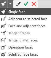
|
If you need to trim all the edges of a solid or surface, you can select the entire solid or surface instead of individual edges. In this case, the name of the selected solid or surface will appear in the Surface faces field. Learn more about the features of selecting a solid or surface... |

The selected faces are highlighted, and their names are displayed in the Surface faces field on the Parameter Panel.
1.Specify the intersecting object or objects. To do this, click in the Cutting object field on the Parameter Panel and select an object in the graphics area or in the Model Tree.
The following are used as intersecting objects:
•a coordinate plane or auxiliary plane,
•edges of solids or surfaces, a connected set of edges, or a set of edges that are contiguous with one another,
•a solid, a surface, or a set of surfaces that are contiguous with one another,
•curves lying on the surface to be trimmed,
•a sketch.
The specifics of specifying intersecting objects depending on their types, as well as the result of the operation for each type, are described in the section “Requirements for an Intersecting Object and Its Effect on the Truncation Result.”
If you need to trim a surface along an isoparametric curve, you can construct this curve without leaving the trimming process. Use the Isoparametric Curve button to the right of the Cutting Object field. Learn more about using isoparametric curves...
The selected intersecting objects are highlighted, and their names are displayed in the Cutting Object field on the Parameter Panel.
The graphics area displays phantom edges that are created during the trimming process.
1.If necessary, you can combine several objects (curves or faces) that do not align precisely with each other into a single intersecting object. To do this, specify the allowable distance between the vertices of the curves or the boundary edges of the faces in the Tolerance field on the Parameters Panel. The range of acceptable values is 0...1 mm.
Objects whose distance is less than or equal to the tolerance will be merged. As a result of the operation, a truncated surface will be created with low geometric accuracy at the junctions of the intersecting objects.
2.A portion of the surface can be removed on either side of the trim boundary. In the graphics area, the trim direction is indicated by an arrow pointing toward the portion of the surface to be removed. To change the trim direction, click the Change Trimming Direction button on the Parameters Panel.
3.You can hide or keep visible the body or surface used as the intersecting object. The Remove secant object option is used for this purpose.
•Enabling this option means that after the surface is clipped, the clipping object is hidden in the graphics area. It is not possible to display it in the graphics area. If the clipping is removed, the clipping object will become visible again.
•If the option is disabled, the intersecting object remains visible in the graphics area. After the operation is complete, you can hide the intersecting object manually. Learn more about controlling object visibility...
The Remove secant Object option appears on the Parameter Panel if a solid or surface is specified as the intersecting object.
4.You can change the name of the clipping operation in the Properties section.
5.If a new surface is created as a result of the operation, you can configure its display settings using the Displaying group of elements located in the Properties section. Learn more about configuring the color and optical properties of objects...
6. To complete the operation, click the Create Object button.
Depending on which operation result is selected (see above), the following occurs in the graphics area: either a new truncated surface appears, or the original surface is modified to reflect the truncation.
A new element appears in the Design Tree, representing either the surface created by the truncation or the truncation operation itself.
|
If the operation results in several separate surfaces, then after completing the operation, the process of changing the set of surfaces is started. Select the surfaces that you want to keep. Details... Each of the resulting surfaces is a separate object. You can independently change their colors, hide them or move them into layers. But they will be registered as created by one feature, i.e. they will all change in case you edit the plotting feature. |

3.To complete the operation of the command, click Finish  .
.
|
If you've selected a solid or its faces as trimmed object, then trimming may result in disrupting its integrity. More about solids with disrupted integrity... |
See Also
