|
Requirements to the section objects of the trimming operation |
Scroll |
If during performing trimming operation Objects of various types can be used as intersecting objects. Notes on selection of sectioning objects and the resulting truncation results are described below.
In the case of a faceted trimmed surface, the trimming boundary is also considered fully defined if the sectioning object does not intersect all of it, but one or more faces, and the extreme points of the intersection line lie on the edges of these faces. In this case, the edges or parts of the edges are included in the trimming boundary. An example of such boundary is shown in the figure. Here, the trimmed object is a three-faced surface, and the sectioning object is a broken line whose segments lie on its edges.
|
|
a) |
b) |
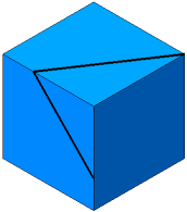
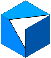
Example of trimming of a three–faced surface
a) surface to be trimmed and sectioning object. b) result of trimming
Various types of objects can be used as intersecting objects. In some cases, you can specify multiple intersecting objects of the same type, such as multiple faces or multiple curves lying on the surface to be truncated.
The specifics of selecting intersecting objects and the resulting trimming results are described below.
Coordinate plane or construction plane
Only one coordinate plane or auxiliary plane may be used for clipping.
Truncation occurs along the line of intersection between the plane and the surface being truncated.
A face, a connected set of faces, or a set of faces that meet at their edges
For trimming, you can use a face, a connected set of faces, or a set of faces from solids or surfaces that are adjacent to one another.
Trimming occurs along the line of intersection between the selected faces and the surface being trimmed.
In a single step, you can select a face or a group of faces that satisfy a specific condition. To specify the condition, use the Quick Access Toolbar.
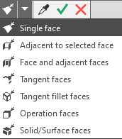
Selecting faces based on conditions
After the condition is set, specify the desired face.
You can use solids or surfaces for trimming.
Trimming occurs along the line of intersection of the trimmed surface with all faces of the selected solid/surface.
If, during further editing, the solid/surface will have new faces, the trimming line will change (provided that the operations that change the solid/surface are located in the Design Tree above the trimming operation).
When the sectioning object is a solid/surface, the name of this solid/surface is displayed in the Sectioning Object field.
Features of specifying a body/surface
Curves lying on the trimmed surface
The following can be selected as the sectioning object:
•spatial curve,
•edge of a solid or surface,
•chain of curves or edges,
•one or several segments of a curve (for example, a broken line),
•several curves and curve segments not connected to each other.
Trimming is performed by the selected curves.
Curves are selected in the graphics area or in the Model Tree. Some objects, such as an edge or a segment of a multi-segment curve, can only be selected in the graphics area.
A single selection in the graphics area can specify a single curve/edge or a group of curves/edges that satisfy a specific condition. To specify the condition, use the elements of the Quick Access Toolbar.
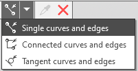
Selecting curves and edges based on conditions
Once the condition has been set, specify the desired curves or edges.
|
The use of curves with subordinate curve objects (projection curve, intersection curve, etc.) has specifics. Details... |

An isoparametric curve can be used as a sectioning object.
If the curve has already been created in the model, select it in a usual way.
If there is no curve in the model, create one without interrupting the trimming operation. To do this, press the Isoparametric Curve button to the right of the Sectioning object field. The operation of creating an isoparametric curve on surface will be started.
If the trimmed surface consists of one face, it will be selected automatically; if it consists of several faces, then specify the face on which the curve should be located. After the curve is plotted, the system returns to the trimming process. The created curve appears in the Design tree and is automatically selected as a sectioning object.
|
If the field Sectioning Object contains previously selected curves, then the isoparametric curve will be added to the list of curves constituting the sectioning object. If the objects contained in the field are not curves, then you cannot add an isoparametric curve to the sectioning object. |
Sketch
Select the sketch in the Design Tree to make it the sectioning object. You can't use several sketches for a single trimming.
Trimming is made by the line of intersection of the surface being trimmed with the surface generated by extrusion of the sketch in a perpendicular direction to its plane.
A sketch may contain one contour, closed or open, or several closed contours. Contours should not have intersections and self-intersections. Example of trimming using a contour in a sketch is shown in the picture below.
|
|
|
a) |
b) |
c) |
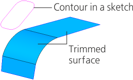
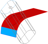
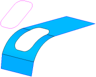
Example of trimming a surface using a contour in a sketch
a) surface to be trimmed and sectioning object; b) objects after selection; c) result of trimming
