|
Graphic documents |
Scroll |
1.It is now possible to limit the area of the model projected onto the drawing. This area is defined on the drawing view by two planes parallel to the projection plane of that view: the first passes through the point on the model closest to the viewer, and the second lies behind the first. If the view is a section, the first plane coincides with the sectioning plane. The user specifies the distance between the planes—either by entering a numerical value or by indicating the position of the second plane on another projection of the same model.
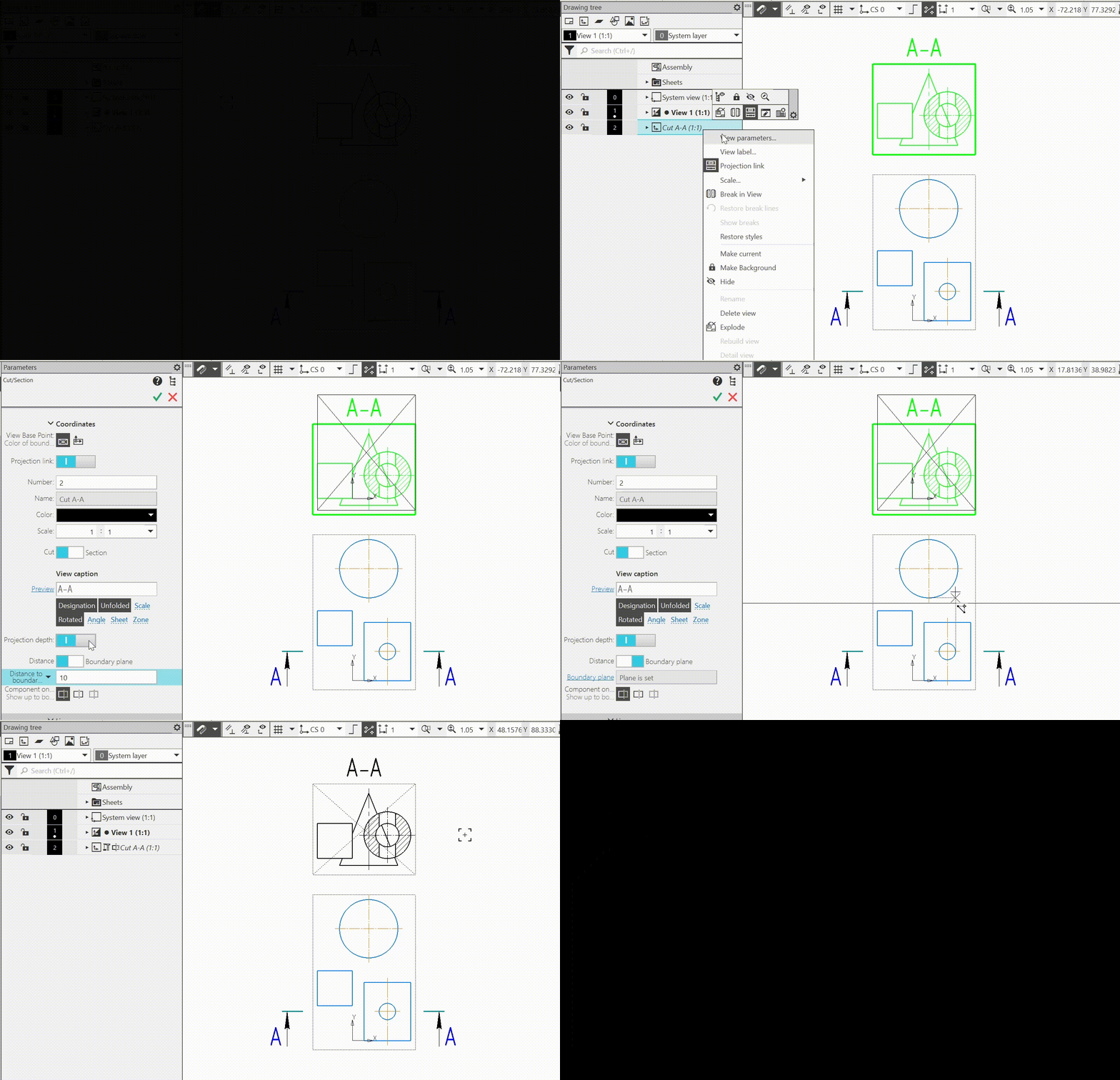
Enabling and configuring the projection depth for a section
1.In the list of model objects displayed for an associative view in the Drawing Tree, you can include only visible objects—that is, objects actually shown in that view. Objects not present in the view—for example, those hidden by others or located outside the local view boundary—are excluded from the list. This simplifies working with assembly model drawings containing a large number of components.
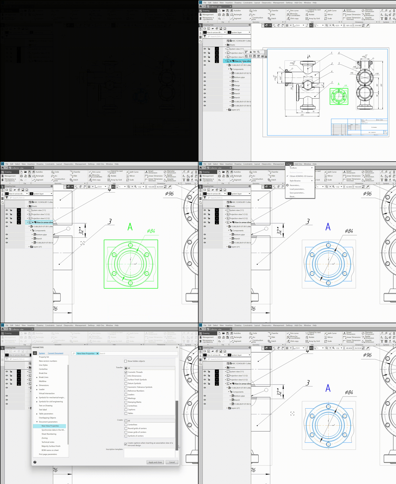
Include only those model objects in the Drawing Tree that are actually present in the view
2.A new constraint called "Object Symmetry" has been added, which can be applied to objects using the new Object Symmetry command. To apply the constraint, you must specify an axis of symmetry and two objects. Objects can be individual elements (line segments, circles, etc.) or entire composite objects (rectangles, slots, etc.). The types of the specified objects must match, but there are some exceptions; for example, a line segment and an axis, or a circle and an arc, can be made symmetrical. As a result of applying the constraint, the objects are positioned symmetrically relative to the axis and become identical in size.
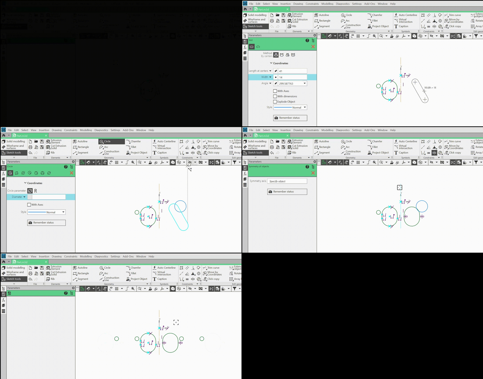
Symmetrical placement of objects in a sketch
3.The Mirror command has been updated:
•It is now possible to specify the SK or LSK axis as the axis of symmetry,
•The constraint that occurs when using the command in parametric mode now depends on the object type: as before, a constraint is applied to points «Symmetry of points», and a new restriction on other types of facilities «Symmetry of objects».
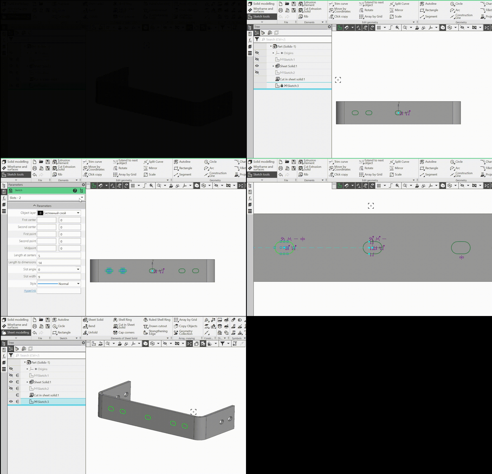
Mirror image of objects
4.The process for adding linear dimensions with extension lines tangent to circles or arcs has been improved:
•the Linear Dimension command now allows you to select Vertical and Horizontal types for such dimensions (previously, they could only be Parallel to Object and, accordingly, show the minimum distance between circles, the maximum distance, or the distance between centers),
•In the Line Dimension from Segment to Point command, you can now select a circle or arc as the first object, and buttons have been added to choose the dimension placement option: from the segment to the nearest point on the circle, the farthest point, or the center.
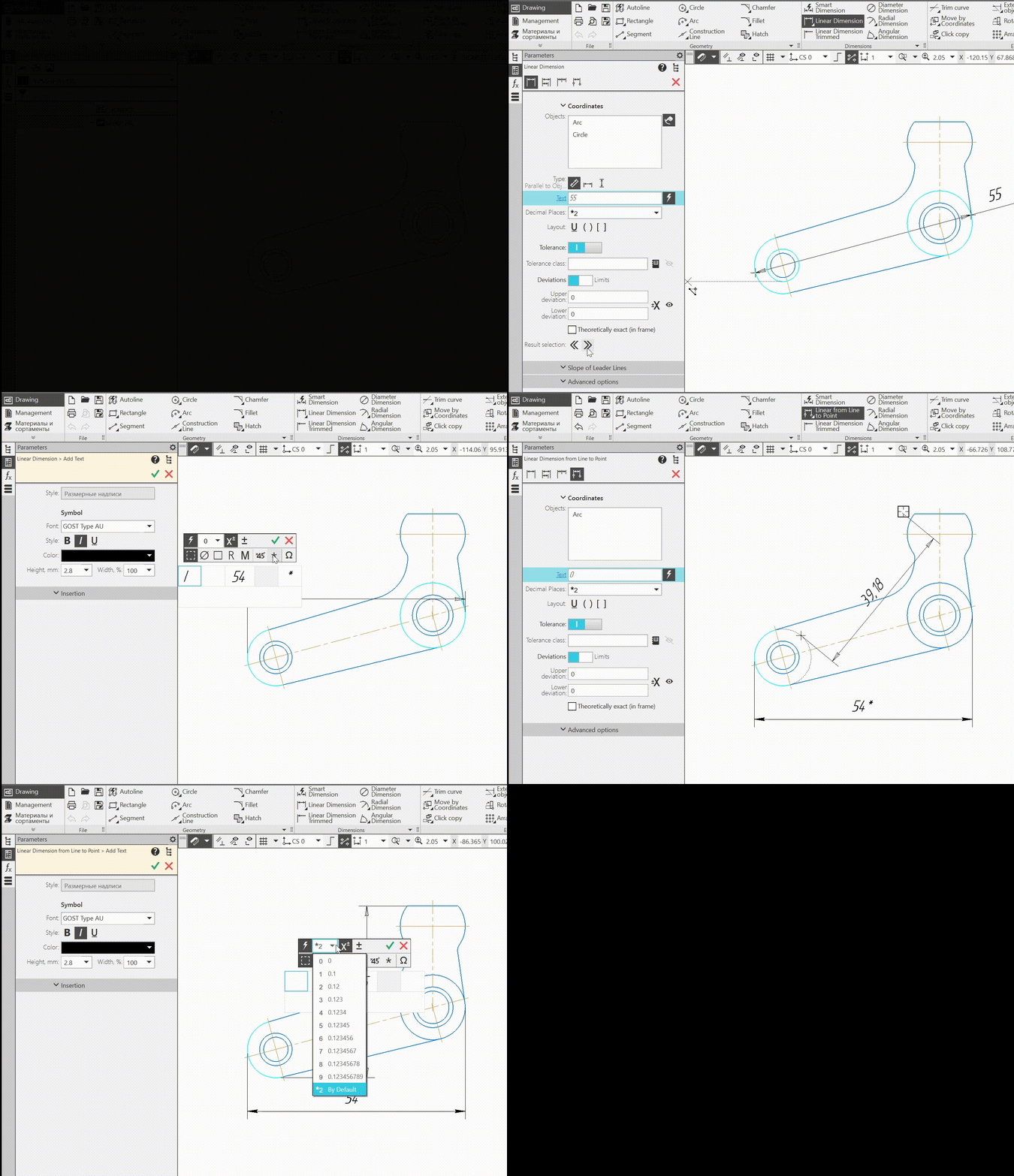
Linear dimensions with extension lines tangent to arcs
5.The commands for creating arrays and copying graphic objects have been updated:
•To make it easier to access the array editing command, it has been added to the context panel that appears when an array or individual objects within it are selected.
•Truncating or intersecting a line segment, circle, or arc within an array no longer removes that object from the array. In the case of an intersection, one of the resulting parts of the object remains within the array.
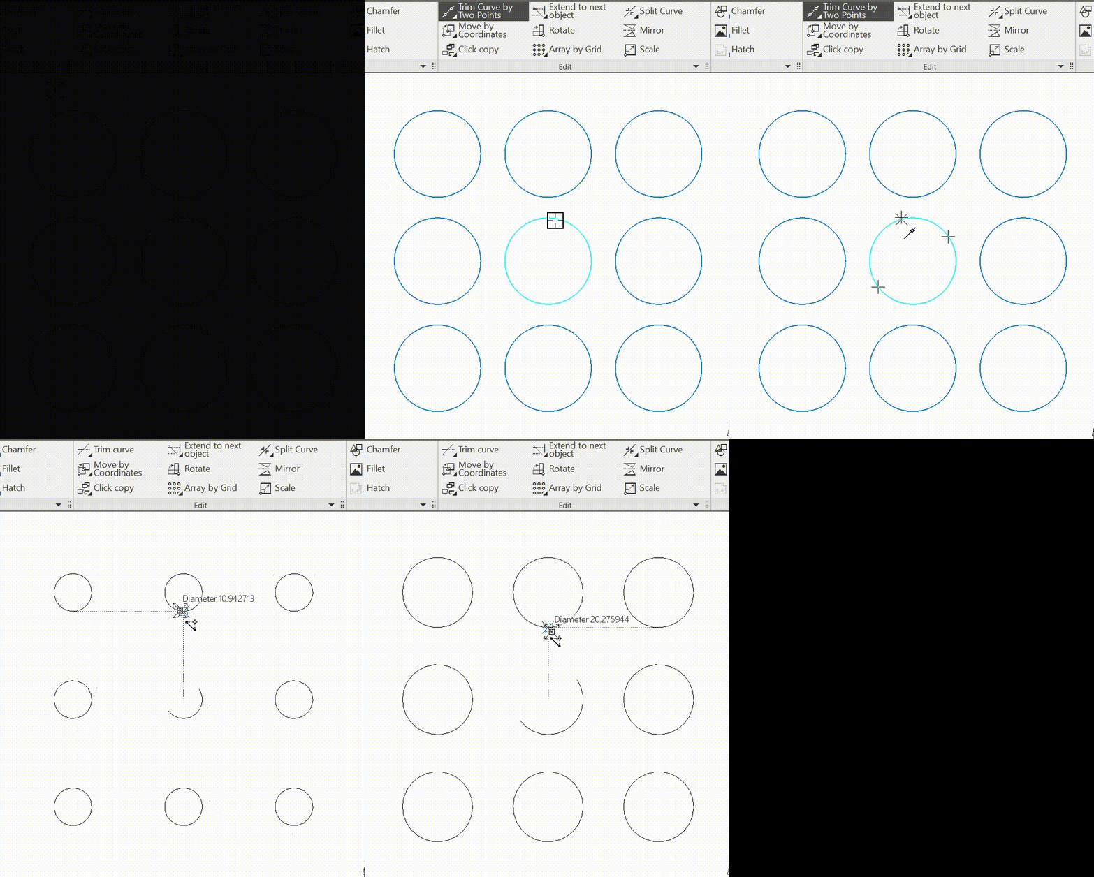
Truncating a circle that is part of an array
•Array by Grid command:
•Added the ability to specify grid axis directions by selecting linear objects in the document (when working in sketch mode, you can also select linear objects in the model); the array maintains a link to the specified objects and is redrawn when their position changes;
•Added options for the array construction result: with removal of copies inside the grid and with placement of copies only along the axes.
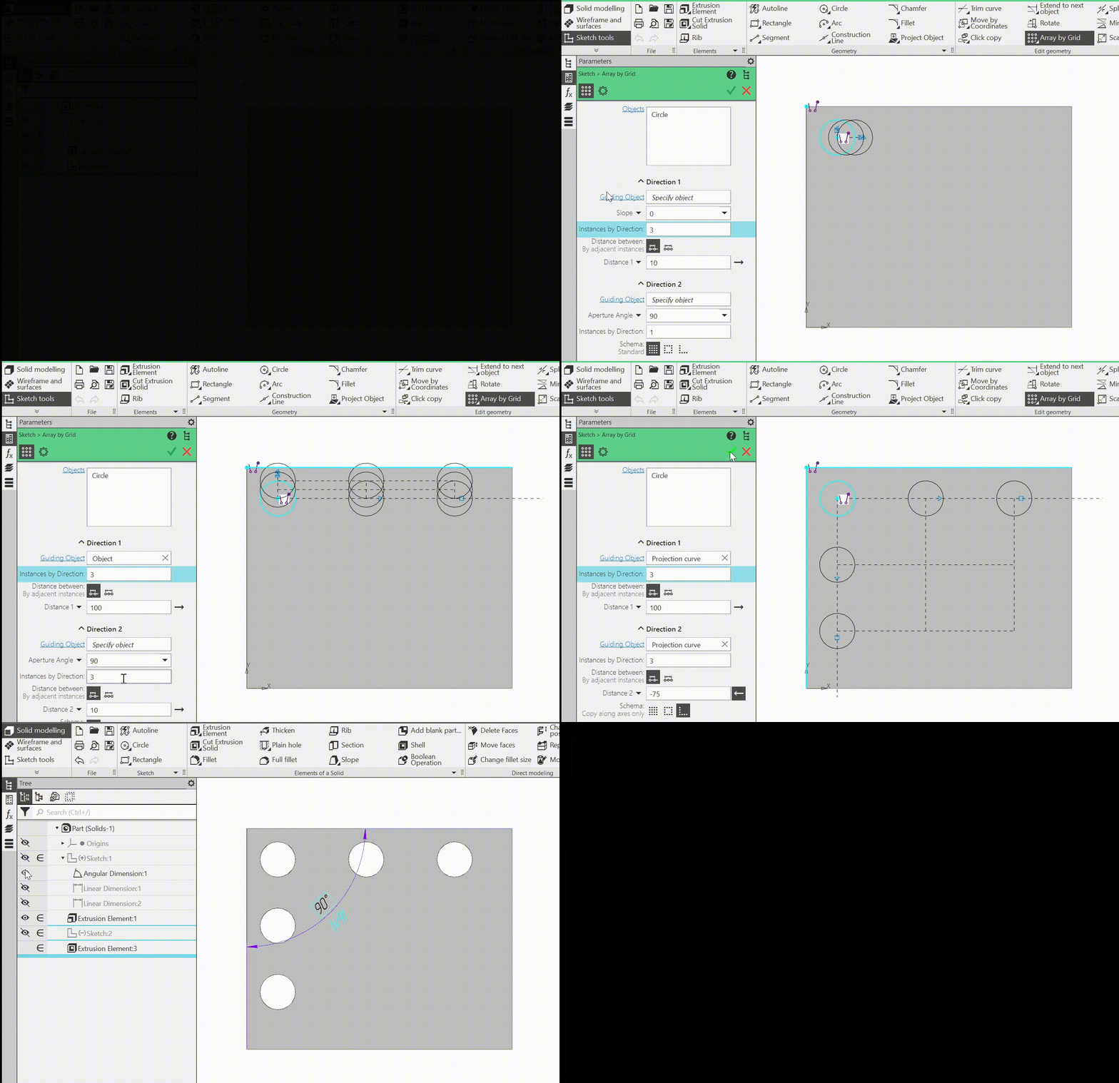
•Define grid axes by specifying model objects; place copies only along the axes
•Added the ability to enter and display expressions for calculating array parameter values in the corresponding fields of the Parameter Panel.
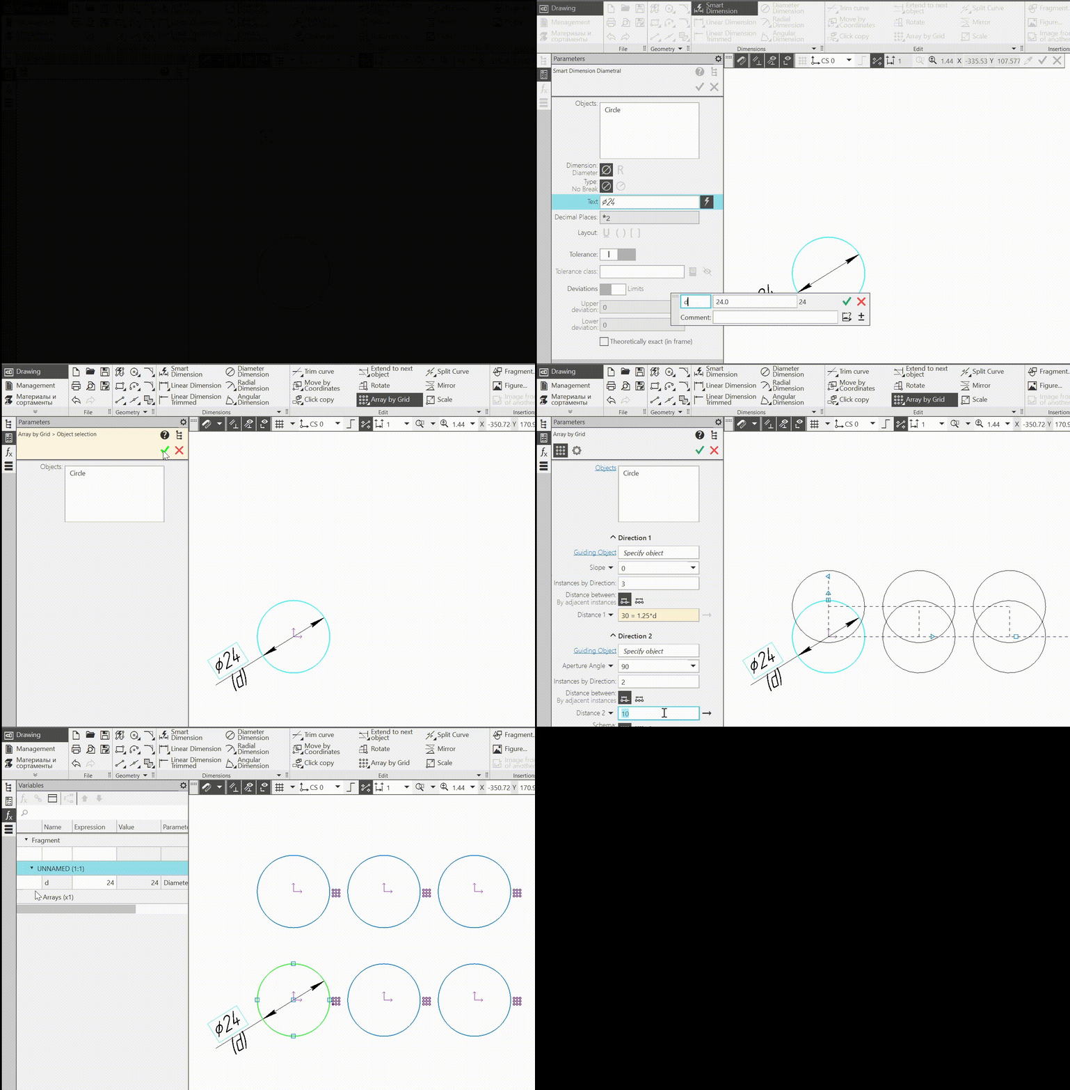
Setting array parameters using expressions
•In the Copy by Grid command, the controls on the Options Panel have been rearranged to make it look more like the Options Panel in the Array by Grid command.
6.New options for specifying surface roughness: enclosing the designation in parentheses and adding an asterisk after it. If necessary, the field containing the "asterisk" can be edited by entering any text. These options are also available when creating a surface roughness designation in the model.
Note: The option to add a text label to the surface roughness designation, which was previously used to enter an asterisk or other text after the designation, has been removed.
1.New features for working with macroelements:
•A command to exclude geometry from a macroelement has been added. The command moves selected objects from the macroelement to the document without changing their position.
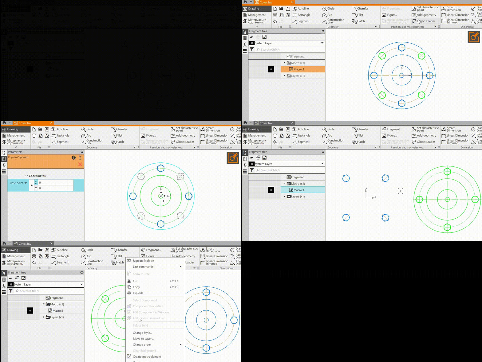
Excluding objects from macro elements
•Objects inserted into a drawing from the clipboard can optionally be merged into a macro element during insertion.
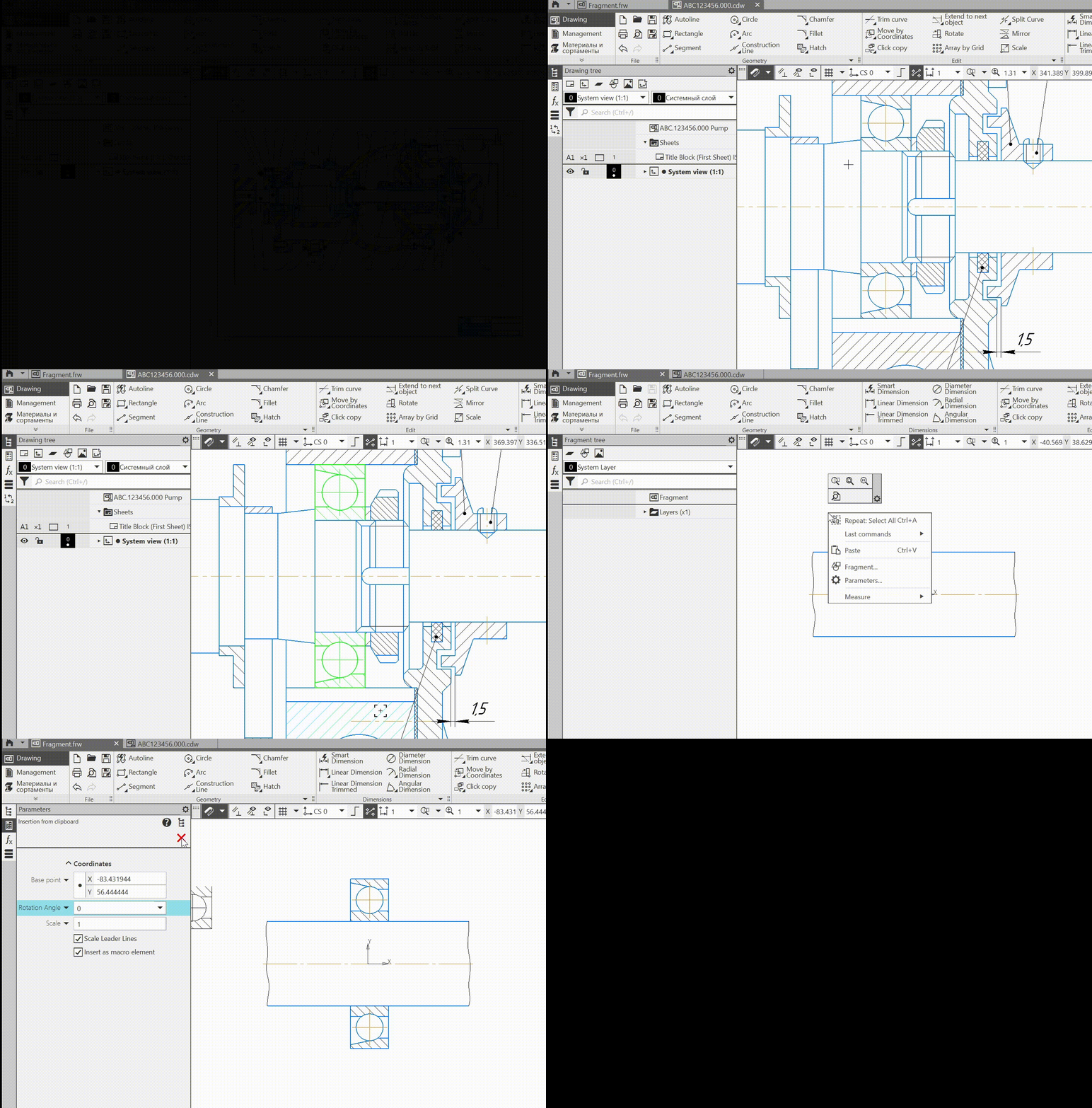
Inserting objects from the clipboard while combining them into a macroelement
2.The presence of zero-length segments in a document is no longer flagged as an error. Such segments may appear, for example, as a result of editing a parametric image.
3.In an associative drawing, it is now possible to create references to the properties of assembly components projected into that drawing.
4.When working with parametric drawing documents, you can now enable or disable the display of variables in dimension callouts. To do this, use the same command and key as when working with 3D models: Names of variables in dimensions, <F11>. (The Display Constraints command no longer affects how variables are displayed in drawing documents and sketches.)
1.Dynamic highlighting—highlighting an object when the cursor hovers over it—now also occurs when no command is running and when an object snap is triggered. A delay setting has been added for dynamic search, i.e., specifying the time (in ms) that the cursor must remain over an object before it is highlighted.
2.When configuring a line style containing a fragment, you can enable the addition of dashes at the beginning and end. As a result, a line with this style will start and/or end with a dash, and a multi-segment line, such as a polyline, will have no gaps between segments. Previously, there could be a gap at the beginning and/or end of a line (segment), which reduced its visually perceived length.
7.Now, when creating a linked dimension, the dialog for setting its value does not appear if the value cannot be changed—that is, when the dimension is informational (previously, the dialog always appeared).
8.If you hover the cursor over the constraint icon superimposed on an object, a tooltip with the constraint name appears on the screen.
9.Parallel processing of associative types has been removed.
