|
3D modelling |
Scroll |
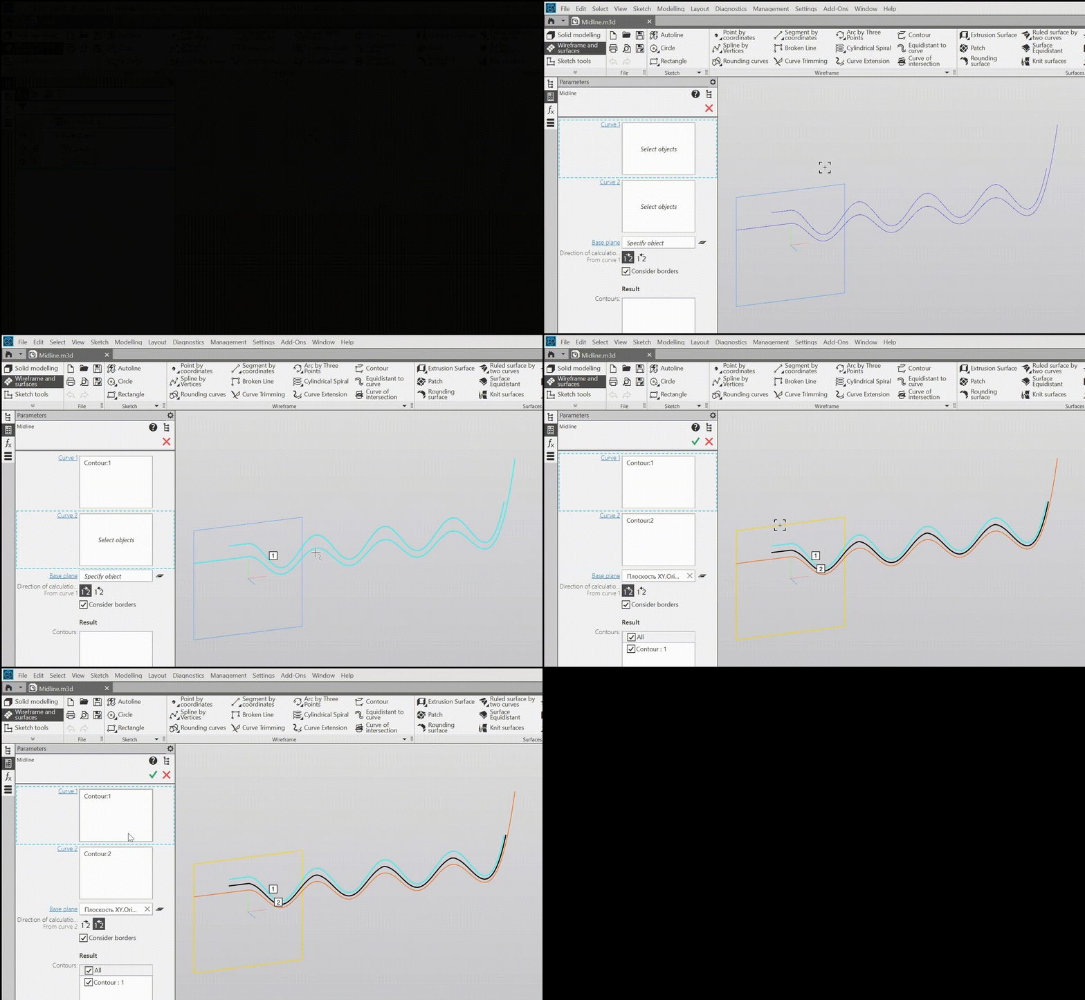
1.The Middle line, command has been added, designed to build a curve in the model, which is the geometric location of points equidistant from two flat curves. To execute the command, two curves and the plane on which they will be projected are set. The middle line is created in the same plane.
Selecting model objects by properties
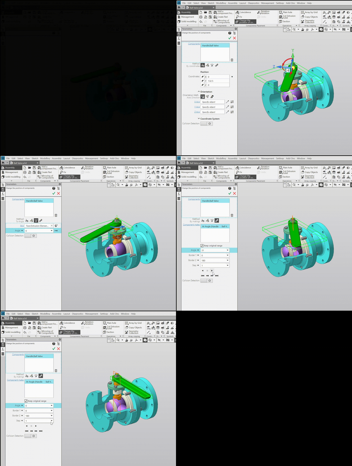
2.The Change the position of components command has been added. It allows you to change a component's position in space in various ways:
•setting the position and orientation relative to the selected reference frame,
•a translation in a specified direction by a specified distance or a rotation around a specified axis by a specified angle,
•for components involved in the To Distance and At Angle constraints—movement according to the constraint parameters; this method also allows you to simulate the movement of a component using animation.
To change the position, you can select multiple components at once.
Just as when using the commands Move Component/Rotate Component, constraints applied to a moving assembly component may fully or partially restrict changes in its position and cause other components to move; it is also possible to monitor collisions between moving components and the rest of the assembly.
Changing the position of a component in an assembly
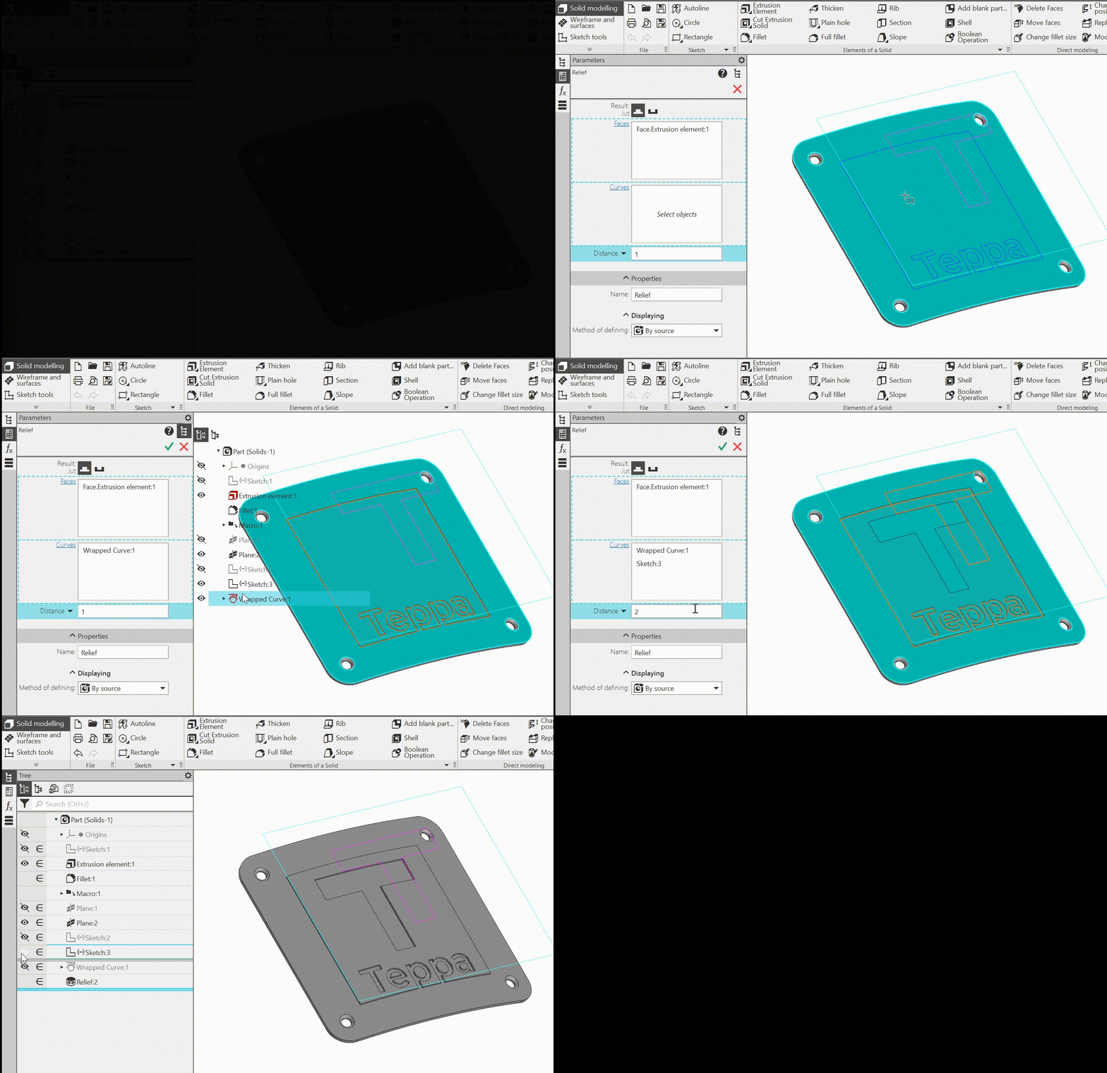
3.The Relief command has been added, allowing you to create a relief pattern on the faces of a solid by projecting closed contours (spatial curves, edges, sketch lines) onto them and then adding or removing a layer of material within the resulting areas.
Creating texture on the edge of the body
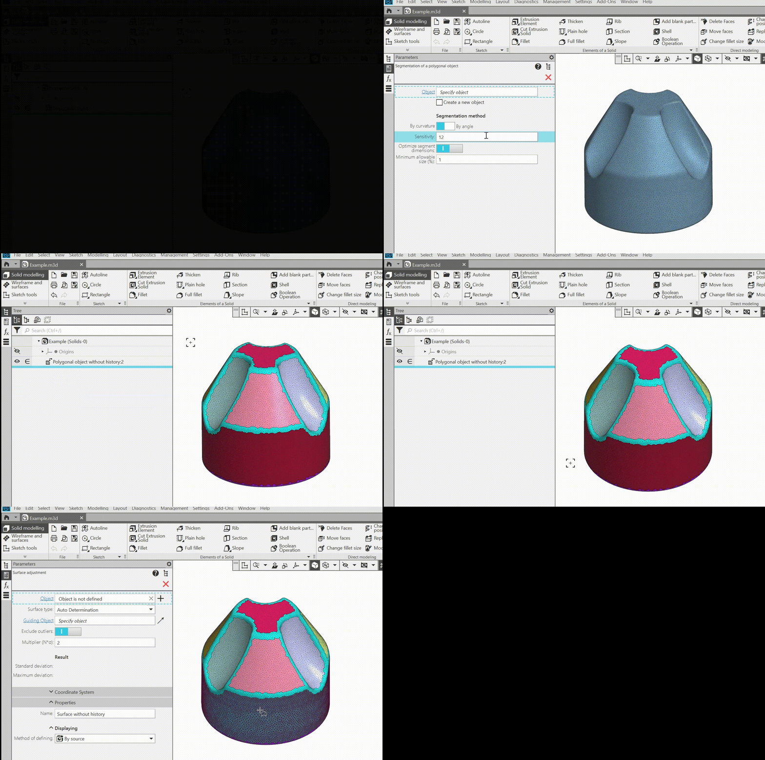
4.Command Segmentation of a polygonal object added, A command that divides a polygonal object into segments. A segment is a connected set of triangles characterized by relatively constant curvature at the vertices or by a constant angle between adjacent triangles. This command allows you to select areas within a polygonal object that are similar in shape to analytical surfaces (plane, cylinder, sphere, cone, torus).
Segmenting a polygonal object and fitting one of the resulting parts
5.The Select by Properties command has been added. It allows you to select objects of various types in the model that possess specified characteristics. For example, you can find components in an assembly that meet specific size criteria and have specified properties, or curves of a specific type located on a specified layer, or operations of a specific type that have variables with specified values, and so on. You can specify either a single condition for selecting objects or several at once. To combine conditions with a logical operator «And», they should be defined within a single conditional block. Blocks are joined using the «OR».
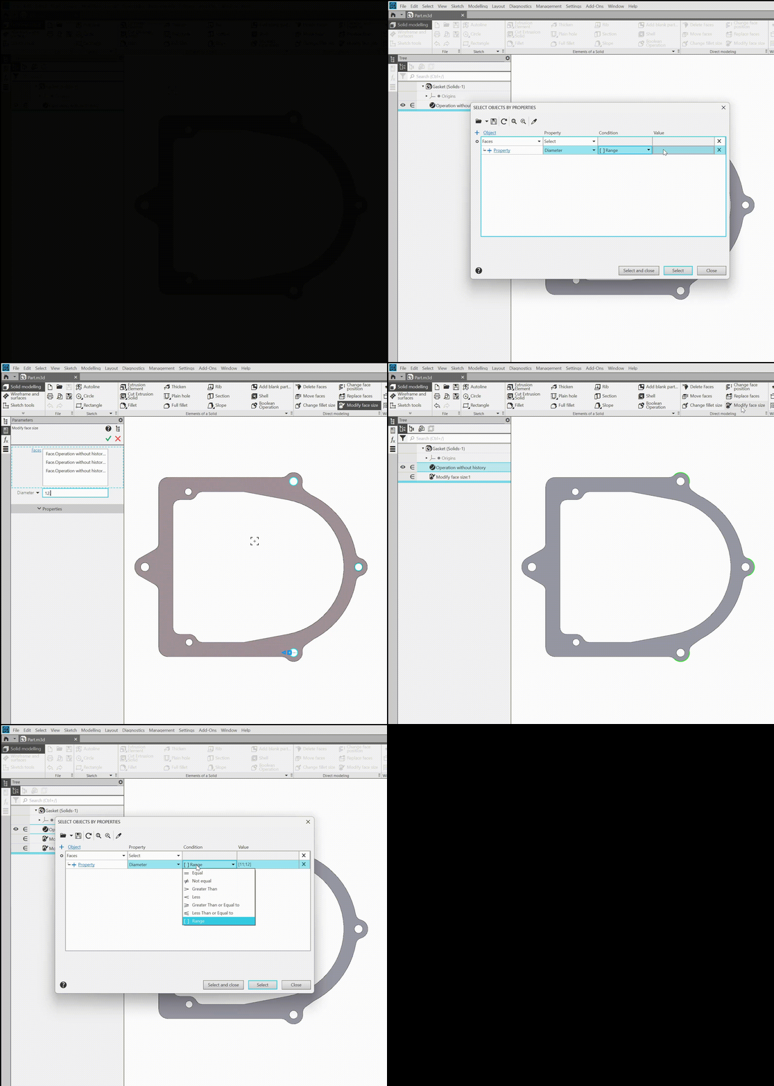
Selecting model objects by properties
6.A new command, Update version of selected operations, has been added, allowing you to rebuild the specified operations using the new algorithms available in the current version of KOMPAS-3D.
7.The Rounding Surface command has been updated:
•New methods for determining surface width have been added:
•Tangent to surface — the fillet surface is constructed so that, in addition to the original surfaces, it also touches the surface specified by the user.

Example of constructing a fillet surface using the Tangent to surface method
•By boundary curves — the fillet surface is constructed so that its boundaries coincide with the user-specified curves lying on the source surfaces.
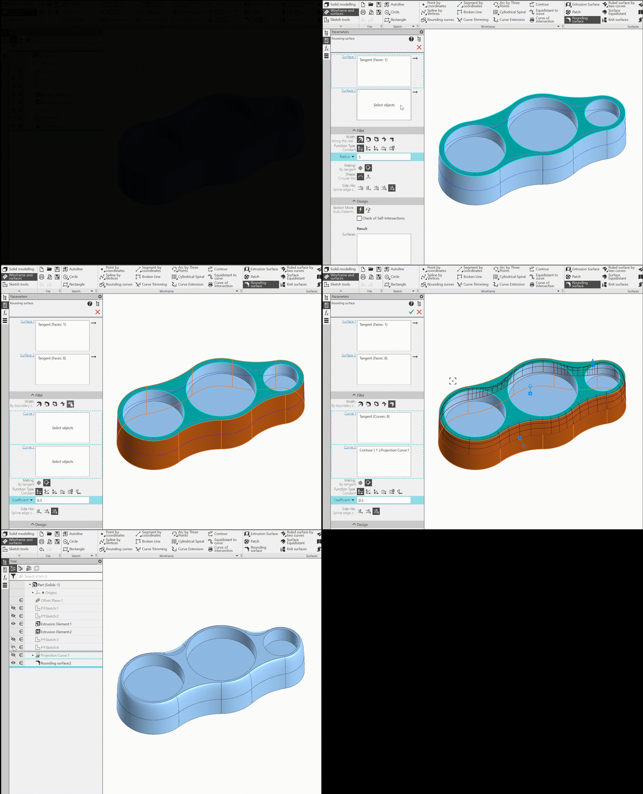
Example of constructing a fillet surface using the By boundary curves method
•A new method for setting rules to change parameter values has been added — By values at points. With this method, the user specifies points along the section’s path, sets the desired parameter value at each point, and defines the interpolation method between points: linear or spline interpolation.
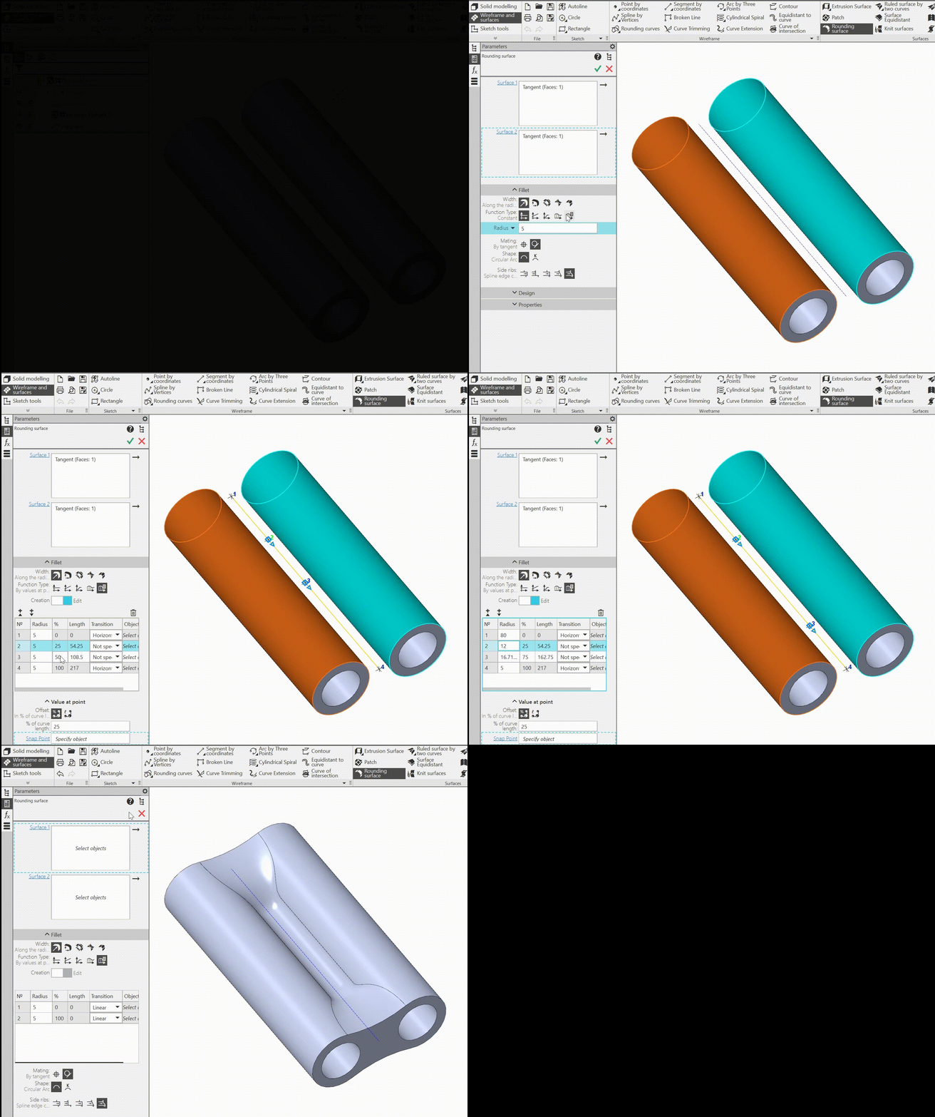
An example of constructing a rounding surface with specified radius values at the points of the section movement line
8.It is now possible to create a special type of variant in the model: a geometry composition variant. A geometry detail variant is designed to isolate a portion of the source model’s geometry so that it can be loaded separately from other objects in that model. Using specially prepared detail variants in complex models allows you to significantly reduce RAM consumption and improve computer performance when working with large assemblies.
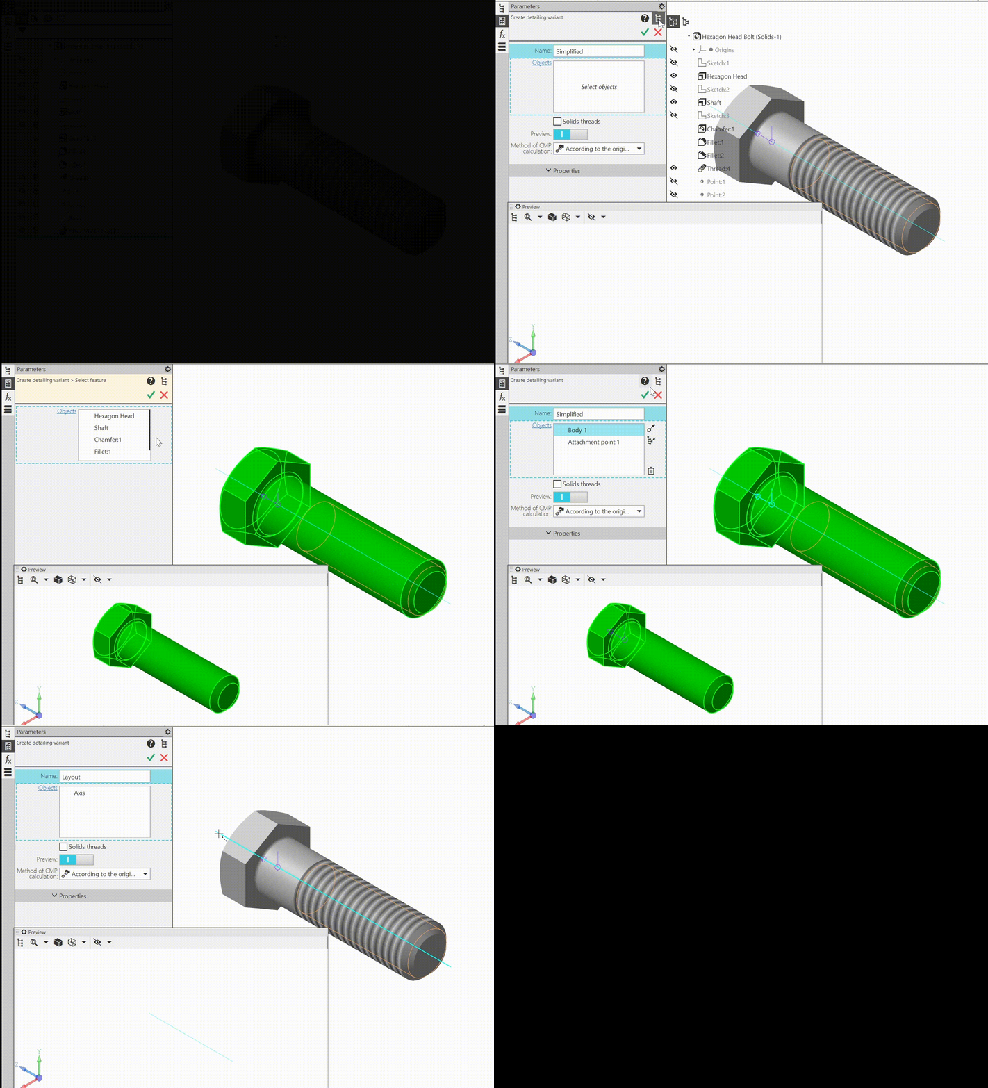
Creating model detail options
9.A new KOMPAS-3D system setting has been added that specifies which variants to apply to assembly components when the assembly is loaded and defines the priorities of these variants. For example, in fastener models, detail variants can be created that represent these fasteners in a simplified form: without chamfers, fillets, or holes. If this simplified variant is set as the priority during configuration, the time required to open the assembly can be reduced (proportional to the number of inserted fasteners), and an assembly drawing can be obtained with image simplifications as specified by the standard.

Specifying the option applied to the assembly's components when it is opened
10.Object selection processes have been improved and refined:
•Filter functionality has been improved:
•It is now possible to define custom filter sets for each command that requires specifying model objects (the list of filters is limited to the object types used in the command), and for situations where no command is running. All created filter sets are saved until the end of the document session.
•Object filtering mode indication has been added: if at least one filter is enabled, a special icon appears in the upper-right corner of the graphics area. Clicking on it disables the filters in the current set (other filter sets, if any, remain unchanged).
•When specifying source objects in various commands, it is now possible to automatically select groups of curves and faces that satisfy a specific condition. For example, you can select a chain of curves and edges by specifying one of the links in that chain; by specifying a face, you can select it and all adjacent faces or all other faces created by the same operation, and so on.
Commands that define the condition for selecting objects are available during the operation—on the Quick Access Toolbar and in the context menu.
Objects selected based on a condition are grouped into a set. The set stores information about the initiating object and the selection condition. Thanks to this, when other objects that satisfy the condition appear in the model, they are automatically added to the set, accordingly changing the result of the operation that uses it. If necessary, the set can be edited, for example, to change the initiating object or condition, exclude certain objects from the set, etc.
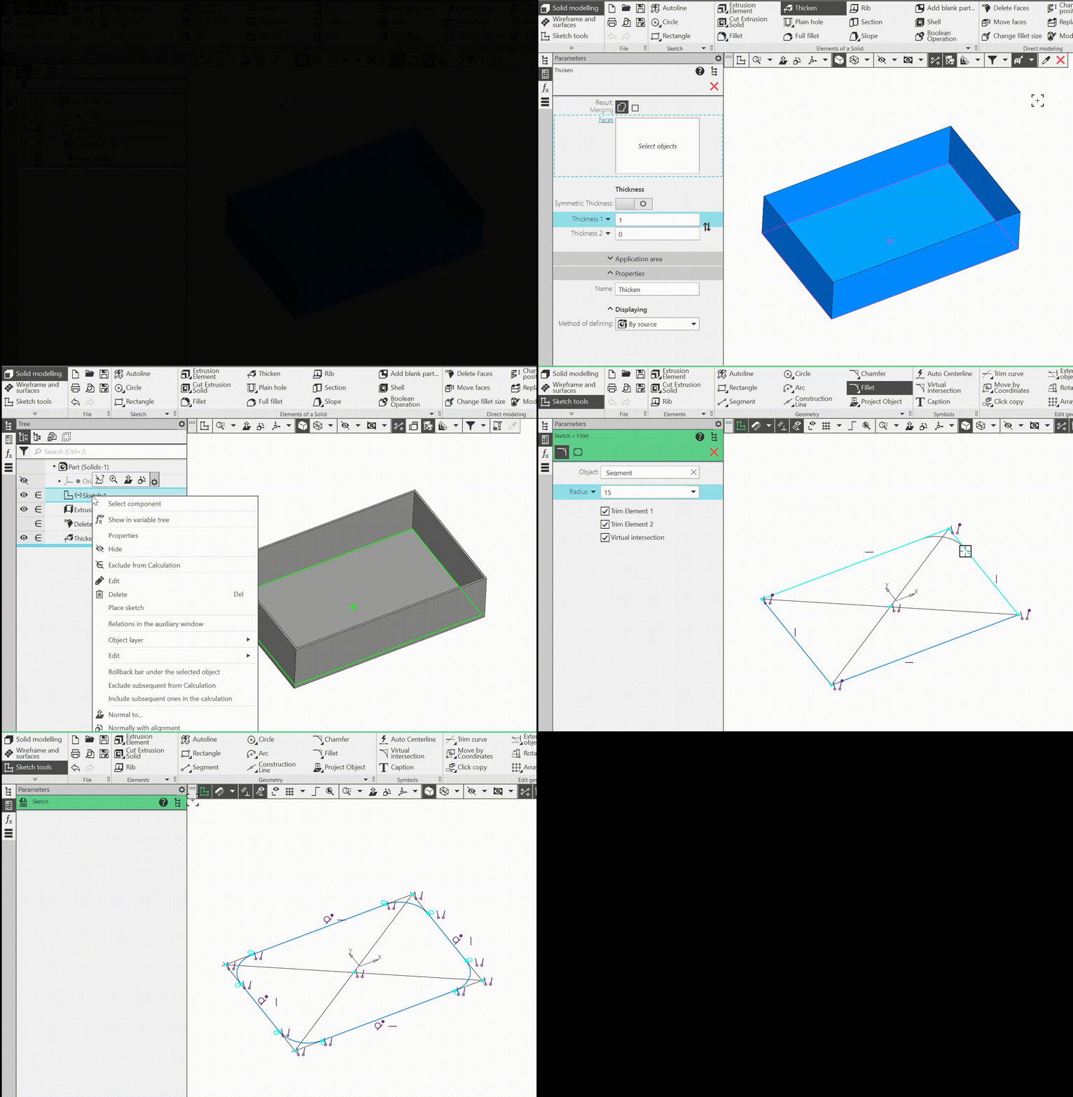
Selecting the face and all adjacent faces
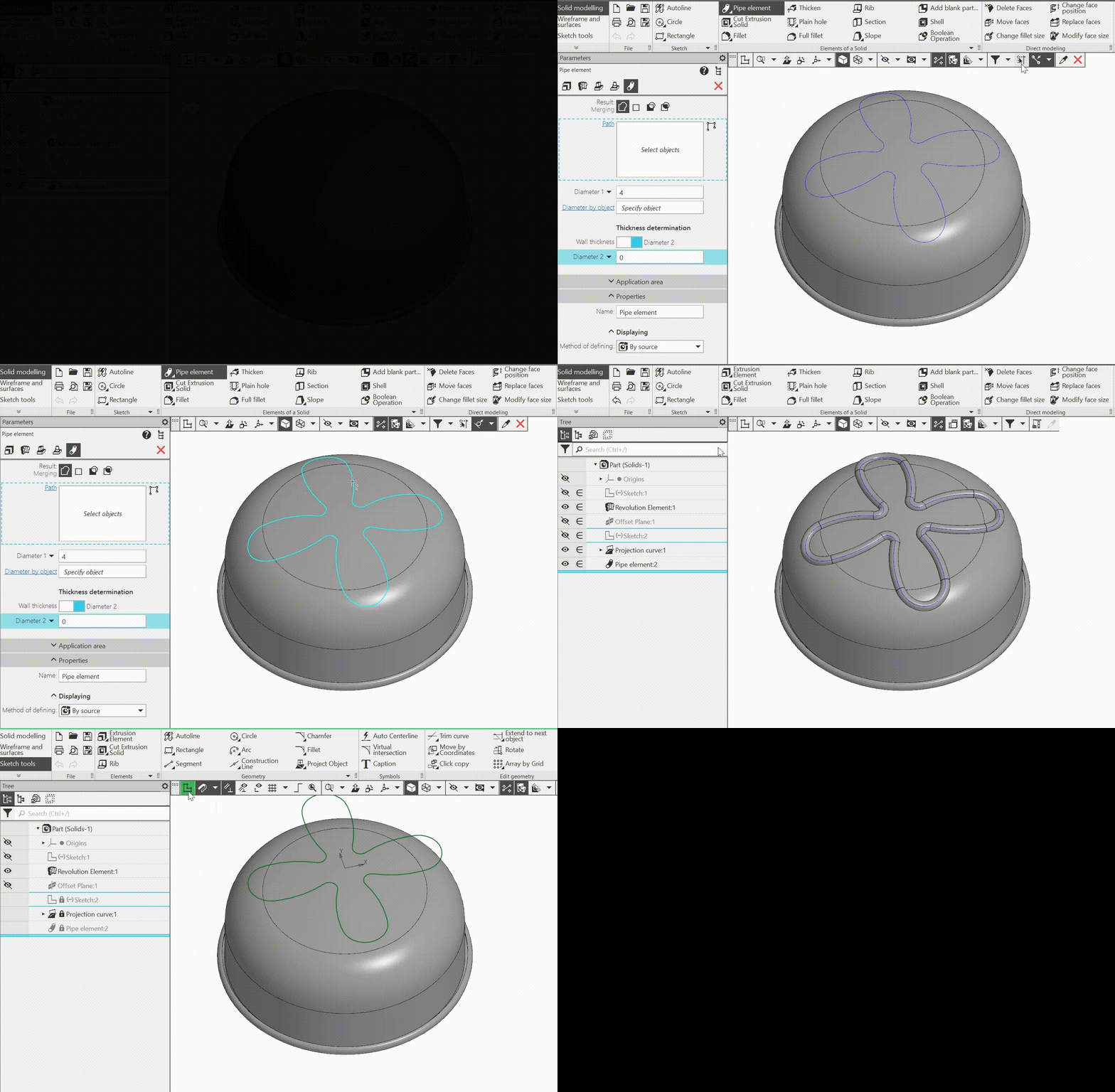
Selecting curves connected by a tangent
11.The Curve Equidistant Line command has been updated: when constructing an equidistant curve by offsetting along a surface, you can now specify multiple faces instead of just one (they must belong to the same solid or surface). Additionally, the ability to trim the equidistant line with face boundaries and extend it to face boundaries has been added.
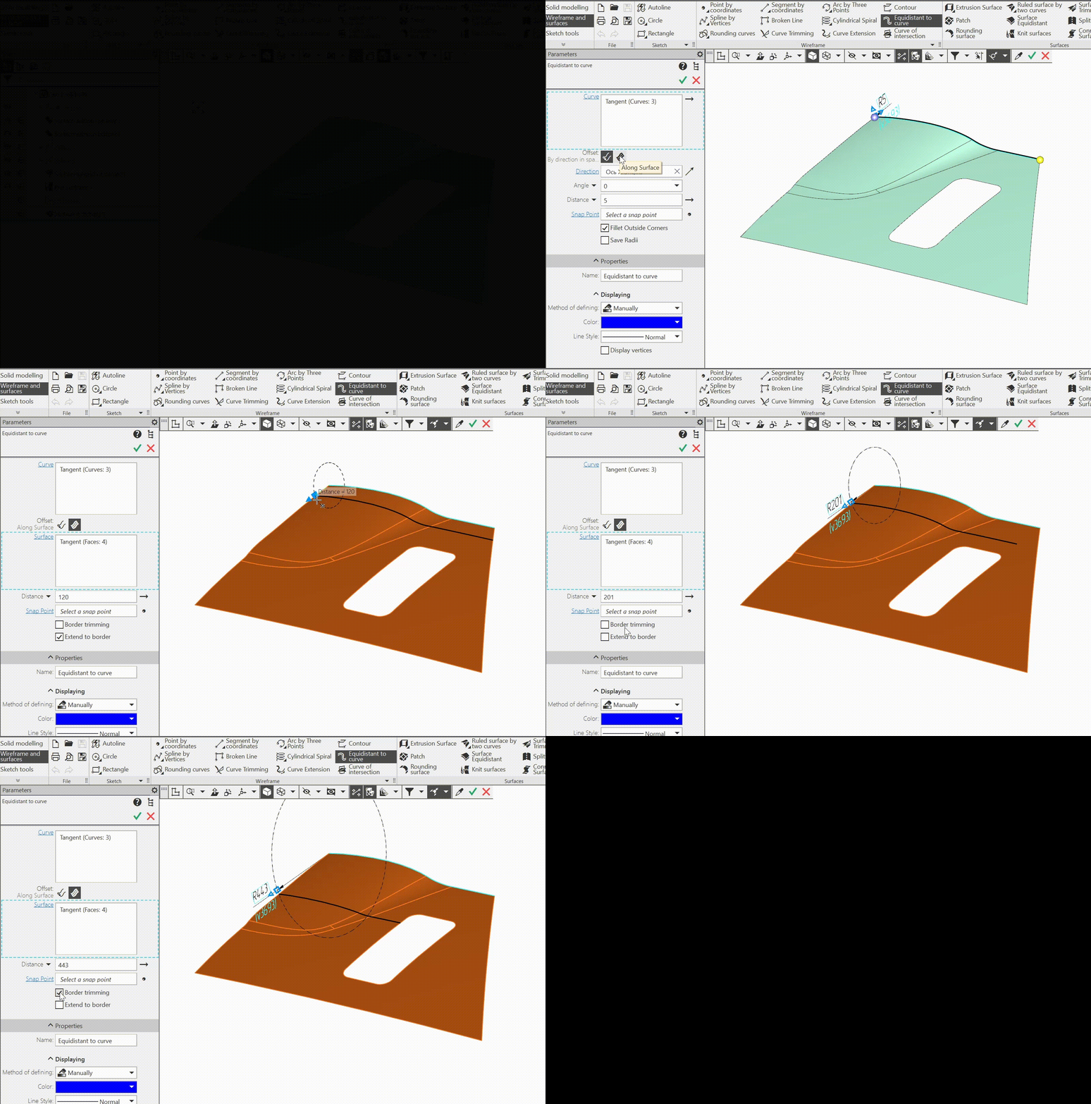
An example of constructing an equidistant line along several faces of a surface
12.The Projection Curve command has been updated:
•The command now works with points and groups of points. It is also possible to project curves and points simultaneously.
•In the By Direction mode, you can enable the creation of curve segments parallel to the projection direction. This allows you to eliminate curve breaks in cases where some of the specified faces cannot be projected onto, such as flat faces parallel to the projection direction.
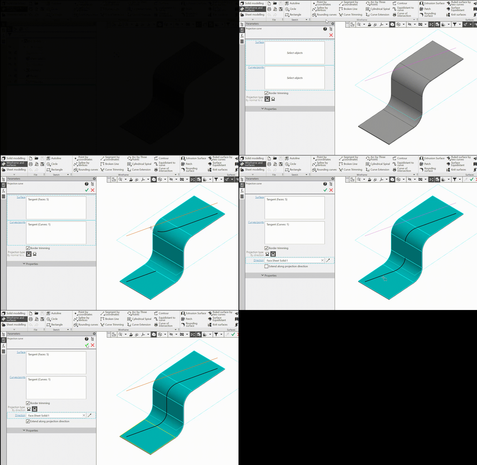
Adding segments of the projection curve that are parallel to the projection direction
13.The hole creation commands now allow you to create multiple holes at once (previously, only one hole could be created per command call).
The position of the holes is determined by points specified by the user. These can be individual points or groups of points: point arrays, sketches with points, etc.
The construction direction for each hole is a line perpendicular to the surface passing through the corresponding point. If the points already lie on a surface, it is determined automatically; otherwise, the surface must be specified manually. Additionally, you can specify a single direction for all holes by selecting an object, such as a line.
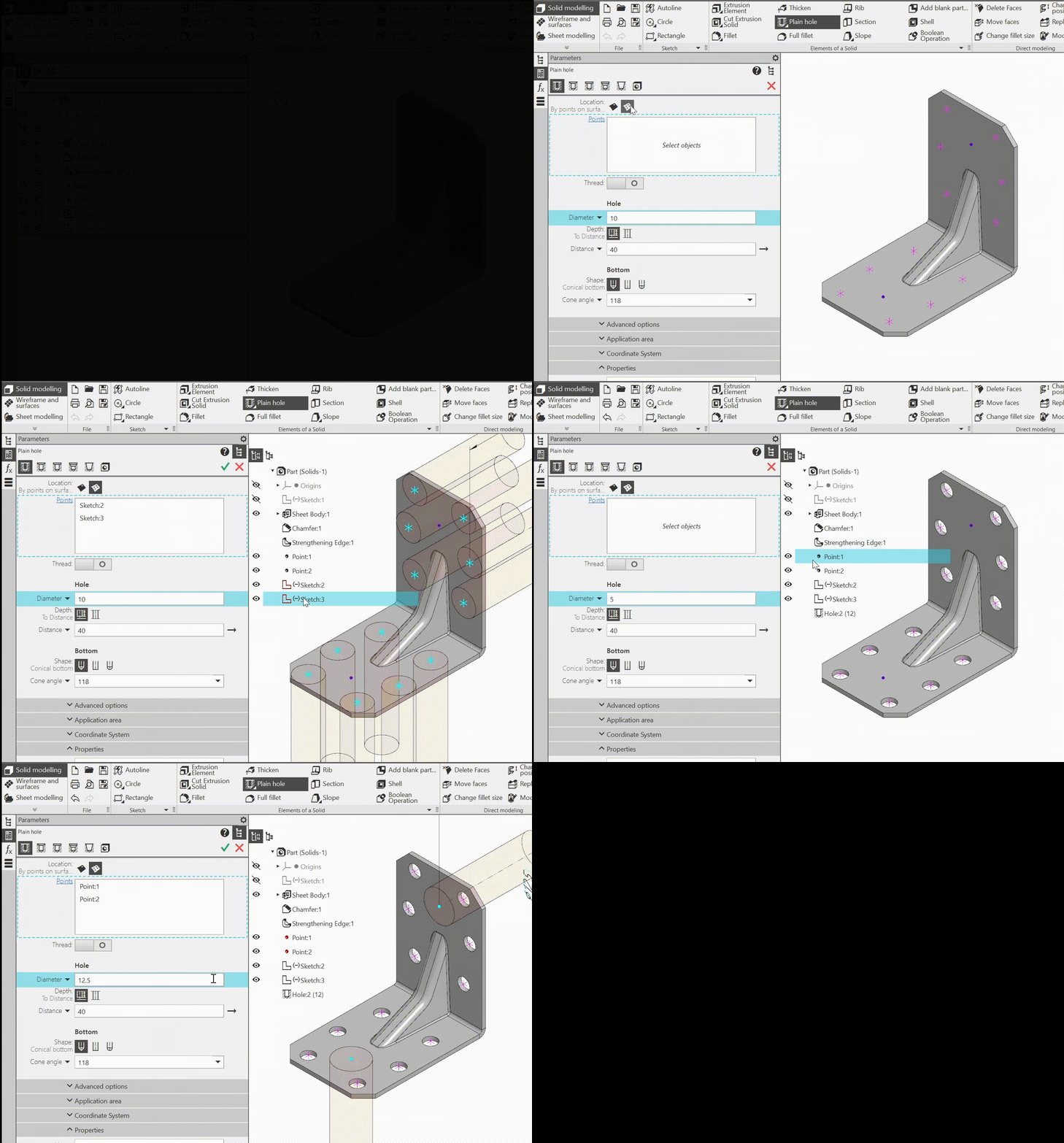
Creating holes based on spatial points and sketch points
14.The following processes have been updated: Distance and Angle, Edge Length, and Area:
•the object created by these processes «dimension» you can now edit it by specifying other model objects for the measurement;
•A standard Create Object button has been added to the process; it completes the current measurement and creates a «dimension» object in the Object Tree (the Create dimension button, which previously created this object, has been removed).
15.Convert to polygonal object command has been updated:
•A conversion accuracy setting has been added: the user can control the maximum linear and angular deviations and the maximum edge length.
•Polygon objects resulting from the conversion are now associatively linked to their original solids and surfaces: if they change, the polygon objects change as well. If necessary, the conversion operation can be undone—in which case the polygonal objects will lose their association with the originals.
•It is now possible to edit the Convert to Polygon Object operation after it has been performed (available if the operation has not been undone).
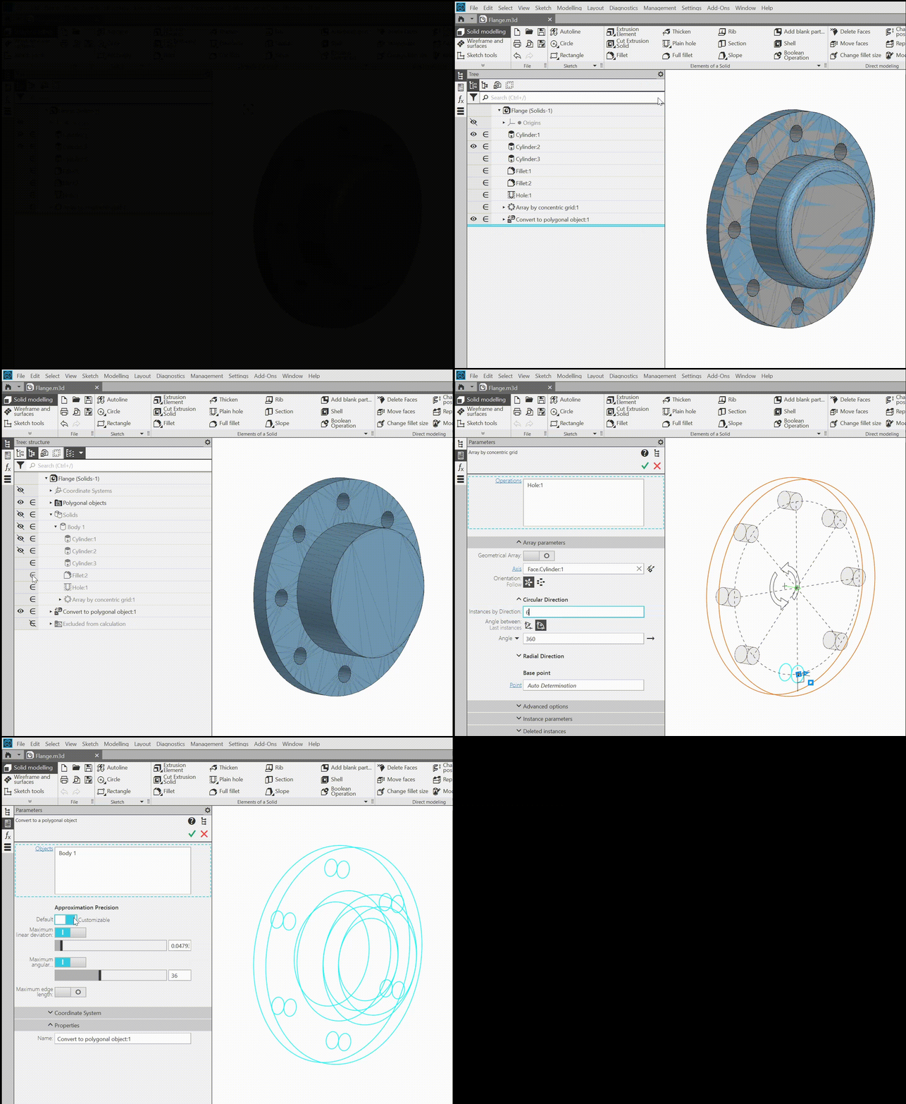
Converting a solid to a polygon object; editing a polygon object
16.Model Family command has been updated:
•It is now possible to add new columns to an existing family table by specifying properties and variables of the template model that are not yet included in the table (previously, this resulted in the creation of a new empty instance table in the same file). The added columns are placed after the existing ones. They are filled in, as before, when editing the family table in the table editor.
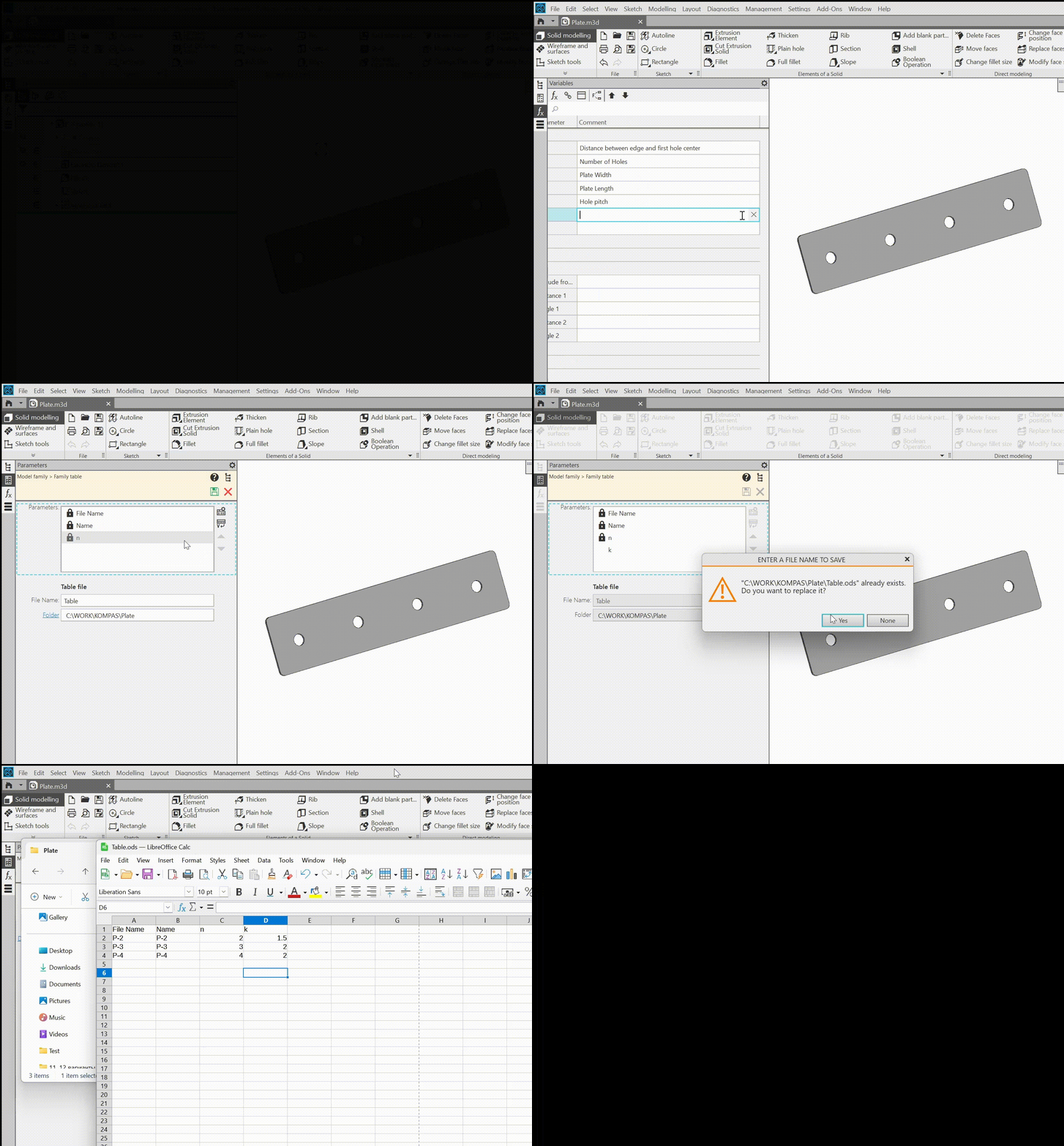
Adding a column to the family table
•A family template can now be a model containing variants (previously this was not possible). The same variants will be present in the instances created from this template.
17.When editing an auxiliary plane, it is now possible to change the method of its construction: the Parameter Panel header displays the same buttons for creating planes as when constructing a new plane. After clicking the desired button, you must specify the plane’s reference objects according to the selected construction method. The relationship between the plane and its dependent objects is not broken as a result of this editing. The plane’s properties set during creation are also preserved.
This feature—changing the construction method—is now also available when editing auxiliary axes.
18.It is now possible to change the direction of the normal of an auxiliary plane during its creation or editing.
19.In the command Surface trimming it is now possible to specify a tolerance for the accuracy of the alignment of curves or surfaces that form a cutting object. This allows you to combine several specified curves or surfaces into a single continuous cutting object—provided that the gaps between them are smaller than the specified tolerance value.
20.When copying geometry, it is now possible to automatically copy threads created on the elements of the body being copied.
21.The Surface by grid of curves command has been updated: a Save direction option has been added, which is available if the V-direction curves are not specified but a constraint condition is defined.
Subsequently, when the shape and/or position of the conjugate objects is changed, this option ensures that the surface is reconstructed based on the fixed mutual direction of the normals/tangents.
22.The diagnostics for 3D models have been improved: they are now more accurate. However, in some cases, this may result in an increase in the number of messages displayed.
Messages about issues that do not prevent the model from being built but require the user’s attention are grouped into a separate category — warnings. Examples of warnings: a message stating that an element does not intersect all or some objects in the scope, a message about a body self-intersection, a message about a body integrity violation. Warnings are displayed in the Tree as an exclamation mark on a yellow background. If necessary, the display of warnings can be disabled.
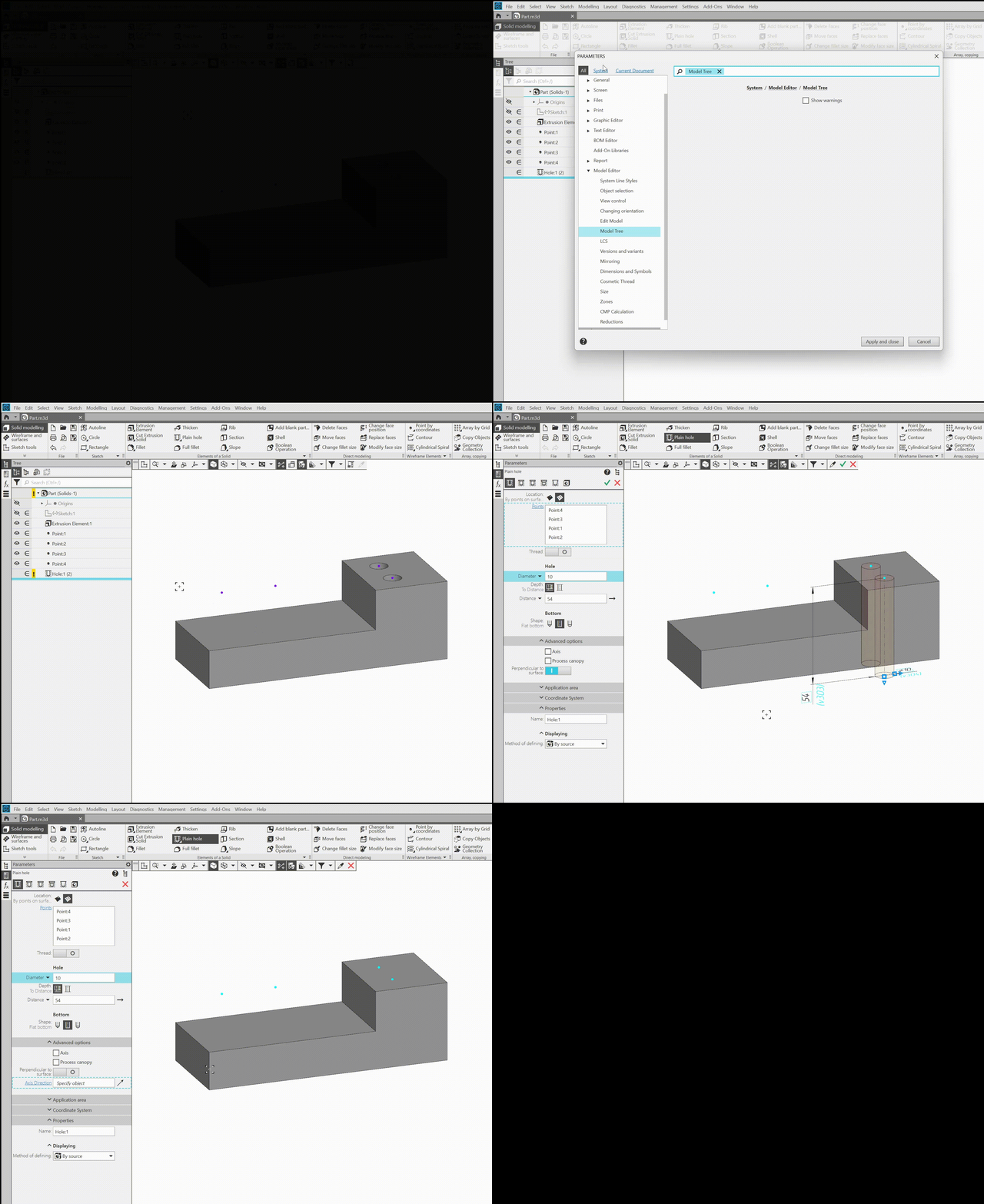
Warnings in the model
23.Improved handling of model object properties:
•You can now set default display settings and a default layer for model solids and surfaces, as well as for assembly components:
•subassemblies,
•parts,
•library components,
•standard parts (for which only a default layer can be set).
•For curves that may include multiple components (such as a contour line, a projection curve, etc.) and groups of points, it is now possible to specify a default layer.
•When inserting a component (other than a standard part) into an assembly, you can now configure the display settings for that component. Previously, these settings could only be changed after the component had been inserted.
24.When working in Sketch mode, the Layers Panel displays both the Sketch Layer Tree and the Model Layer Tree. In this panel, you can modify certain layer settings, such as layer properties. For example, you can make the background layer active. Creating and deleting model layers is not available when working in sketch mode.
25.When taking measurements in sketches, it is now possible to select 3D objects located on the model's background layers.
26.A sketch containing locked dimensions (control dimensions whose values cannot be changed due to constraints or other dimensions) is assigned the status «overdefined» and the corresponding icon (!).
27.The copy management process now includes the ability to view the path to the source document and open that document.
28.It is now possible to open the source document of a contextual link. The corresponding command is called for the model object linked to the assembly via a context link and opens the assembly itself—that is, the document where this link was created during context-based model editing.
29.The default value of the Material property for new assembly models has been changed: this property is now left unspecified by default. Previously, the default material for new assemblies was Steel 10 (GOST 1050-2013). The density value for new assemblies has not changed—it corresponds to steel (0.007856 g/mm³).
30.When dimensions are selected in the Model Tree, their reference objects are highlighted in the graphics area.
31.The creation of a fillet surface has been accelerated. The greatest effect is noticeable when both source surfaces are polyhedral and the number of faces is significant.
32.The process of changing the current variant or instance of a component in an assembly has been accelerated.
33.The generation of family instance files has been accelerated.
34.The data structure has been optimized for models with complex surface geometries that also contain many other objects based on that surface, such as points or holes. As a result, the amount of RAM required to work with such models and the amount of disk space required to store them have been reduced.
35.Highlighting has been implemented in the graphical area of an object selected in a single-line register on the Parameter Panel during command execution. This simplifies the verification of source object selection in cases where all or most of the registers in the command are single-line. Previously, highlighting worked only for objects in multi-line registers.
