|
Menu commands «Select» |
Scroll |
You can use menu commands to select objects in the graphics area Select. The following methods are available:
•Selecting objects by marquee (encompassing and section),
•Selecting component by proximity level (only for assemblies),
•Selecting a component by its source file path (assemblies only),
•Selecting objects by properties,
•Selecting objects by layer belonging,
•Selecting objects using zones,
•Selecting objects based on their visibility.
After selecting several objects with one of the commands, you can call another selection command and continue selecting — the selection is not removed from the previously selected objects.
If you want to cancel the selection, click the mouse in the graphics area or press the key <Esc>.
Selecting objects with a selection window
To select objects using a frame, use the following commands from the Select menu:
 By window — allows select all objects that are entirely within the marquee. The marquee is displayed as a solid line and filled with blue.
 By cutting window — allows you to select all objects that are at least partially within the marquee. The frame is displayed as a dotted line and filled with light green.
Procedure
1.Call one of the marquee selection commands. An on-off switch will appear in the Parameter panel Obstructed objects.
2.Set the on-off switch Obstructed objects in required position:
•Select — to select objects without taking into account their visibility, i.e. both visible objects and obscured objects will be selected.
•Do not select — to select only those objects that are fully or partially visible on the screen; objects obscured by other objects will not be selected.
3.Point the cursor at the first and second vertices of the rectangular marquee. The objects will be selected.
|
To ensure that only objects of certain types are selected when selecting a frame, enable the appropriate filters. Details about using filters... |

4.Continue selecting objects by creating new marquees. Newly selected objects will be added to the objects selected earlier.
5.After selecting all the required objects, complete the command by clicking the button Finish  .
.
Features of selecting objects using a marquee
•During the execution of the frame selection commands, only objects are added to the previously selected ones. Deselection of an object and inversion of the selection are possible after the command is completed. (see. section Specifying objects in the graphic area).
•An object that is in a marquee may include other objects. For example, a broken line consists of edges and vertices, a body consists of edges, vertices and faces, etc. When it is in a marquee, this “composite” object itself becomes specified, and not the objects included in it. For example, when running the command Select — By cutting marquee a part of broken line containing several edges and vertices has been captured in the marquee. As a result, the broken line itself (in full) will be selected, and not its edges and vertices.
•If the model section mode is anabled, then using the marquee you can select only those objects that are at least partially visible on the screen. Objects that are completely within the section part (not displayed on the screen) cannot be selected.
To select an object using the Select — By marquee command , the entire remaining part of the object on the screen must be within the frame. Using the Select — By section marquee has no special features.
•The marquee selection commands can be called while other commands are running — building objects, creating copies, etc. In this case, the object selection command is launched as a subprocess, and after its completion, the system returns to the current command. The selected objects are used to execute the current command, their names are displayed in the fields of the Parameter panel.
In process of creating a copy of geometric objects of model from file the window Model-source is used. The marquee selection commands work in this window the same way as in the main KOMPAS-3D window. When using this window in other processes, the marquee selection commands are not available.
Selecting component by proximity level
When working with an assembly, you can select components by their proximity to an already specified component. To do this, use the Select — Select nearest command. After calling the command, the corresponding controls appear on the Parameters panel.
Procedure
1.Specify in the graphic area or in the Design tree the component relative to which the other component(s) will be selected. The specified component and its bounding box will be highlighted. The name of the component will appear in the Base component field on the Parameters panel.
|
The component can be specified before calling the command. |
1.Select the method for selecting components in the Method field. The following options are available:
•By matings—components linked to one another by relationships are highlighted. The “chain length” of relationships in which the highlighted component participates is determined by its proximity level to the specified component.
The proximity level is set in the Proximity Level field. Its current value (an integer) is displayed in the field to the right. The field is available for manual input. Immediately after the command is executed, the proximity level is 0. Moving the "slider" to the right increases the proximity level. At level 1, components associated with the specified one are selected; at level 2, components selected at level 1 and components associated with them are selected, and so on.
•Select the method for selecting components in the Method field. The following options are available:
•By matings — components are selected that are connected to each other by conjugations. The «length of the chain» of conjugations in which the selected component participates is determined by the level of proximity to the specified component.
The level of proximity is set in the field Proximity level. Its current value (an integer) is displayed in the field on the right. The field is available for manual input. Immediately after calling the command, the proximity level is 0. When moving the "slider" to the right, the proximity level increases. At level 1, components associated with the specified one are highlighted, at level 2, the components selected at level 1 and the components associated with them, etc.
•By size — components that fall within the bounding box of the specified component, scaled with some automatically determined coefficient (the "selecting" box) are selected. The relative value of the coefficient is determined by the level of proximity: the higher the level, the greater the coefficient. The level of proximity is specified in the field Proximity level. Its current value is displayed in the field on the right. By default, the proximity level is 0, in which case the "selecting" box coincides with the bounding box of the specified component. As the proximity level increases, the dimensions of the "selecting" box increase, and the set of components to be selected also changes.
You can control the selection of components that fall into the box. The switch is used for this Secant size/Covering size. By default, the switch is in the position Secant size.This means that components that are at least partially within the box will be highlighted. If the switch is in the position Covering size, then the components that are completely within the box will be selected..
•By distance — components are selected which distance to the specified component does not exceed a specified value.
Set the maximum distance between the specified component and the specified ones in the field Distance.
The selected component, like the specified component, is highlighted in the graphic area. The colors in which the components are displayed depend on the setting. The color specified in the line is used for the specified component Highlighting — Specified object 1, and for specified component — in line Highlighting — Specified object 2.
1.If you want to select first-level components, i.e. those inserted directly into the current assembly, enable the option Select first-level component. In this mode, not individual parts for which the conditions specified in the command are met are selected, but entire components of the first level of the assembly, which these parts are included in.
2.If necessary, the selected components can be isolated, i.e. hide the remaining components of the assembly. For this purpose, use the option Isolate. When the option is enabled, it starts isolation mode.
3.To confirm the operation, click the button Create object .
.
The result depends on the state of the option Isolate:
•When this option is enabled, the specified and selected components remain on the screen, and the isolation mode icon appears in the upper right corner of the window  .
.
•When the option is disabled, the specified and selected components are highlighted in color for selected objects.
Selecting a component by its source file path
When working with an assembly, you can use the paths to the source files of its components to select those components. To select components this way, call the command Select — By source.
|
Command Select — By source can be called during the execution of other commands, for example, the command Replace components |

After calling the command, the following appears on the Parameters panel:
•component table,
•a set of buttons for filtering components by their types,
•search field.
Procedure
1.View the component table.
The table is designed to display a list of components of the current model, the sources of which are external files. By default, the list includes components of all types of all assembly levels.
If several components of any nesting levels have one source file, then the table shows:
•for inserts of the same type — one common line,
•for inserts of the different types — one line for each type.
|
No components are added to the table, excluded from calculation, and components with loading type Empty or Size — neither these components themselves nor the components they contain are displayed. Components included in local inserts are shown in the table if their sources are external files. However, local inserts themselves are not included in the table. |

The table consists of the following columns:
•Type — contains icons that represent the types of components in Model Design tree; the same icons are shown on the filter buttons located above the table (see below),
•File name — contains the names of the component source files,
•Source — contains links to the component source files. Sorting by the values of each table column is available. To sort, click the mouse on the header of the desired column. The order of objects in the column will change, and the icon  . will appear in its title. For example, in case of sorting by column File name The components in the table will be arranged in alphabetical order. Clicking on the column title again will reverse the order of the objects. The title will display the icon
  .
.
2. If you want to keep only certain types of components in the table, click the buttons with icons of these types above the table. The following options are available:
 Part,
Part,
 Assembly,
 Part-blank,
 Standard parts,
 Layout Geometry.
3. To search for a component in the table, enter in the field Search characters that are contained in the path to its source file. Press the <Enter> key. Only components whose paths contain the specified characters will remain in the table.
4. Select the required components using the following methods:
•Select a component row in the table.
When you select another row, the previous selection is reset. Therefore, if you need to select several components, select their rows while holding down the <Shift> or <Ctrl> key.
The selected components are highlighted in the graphic area and in the Model Design tree.
•Specify the component object in the graphic area or the component itself in the Design Tree. Only components whose rows are in the table are available for specifying.
You can specify several components sequentially - the selection of previously specified ones is not canceled.
If the model of the specified component is the source of several insertions of the same type, then all these insertions are selected. The selected components are highlighted in the graphic area and in the Design Tree, and the corresponding rows are highlighted in the table.
|
If a table row contains a source model of several inserts, then when it is selected, all these inserts of all nesting levels will be selected. They will be highlighted in the Tree and in the graphic area. |
5.To confirm the operation, click the button Create object . The command will complete. The components will be highlighted in the graphic area and in the Model tree.
6.To abort the command without selecting components, press the button Finish .
Selecting objects by properties
To select model objects that meet specific criteria, use the Select objects by properties dialog box.
The dialog box is used to set the selection criteria for objects and to select them. The dialog box allows you to select or deselect objects. The dialog box toolbar is used to select the desired operations.
The types of objects to be selected are chosen from the drop-down list in the Object column. The type names are organized into groups. You can select multiple items within a group or the entire group, as well as select items from different groups. Selection criteria are applied to the entire group of selected types. To do this, use the Property, Condition, and Value fields.
The defined selection criteria for objects are grouped into a block (see figure). You can create one or more blocks in the dialog box. Each block includes the selected object types and the selection criteria configured for them.
|
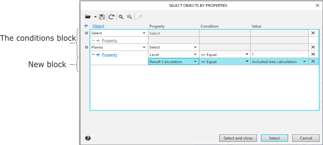
Dialog for selecting objects by properties
After applying the settings, the following occurs: The model is searched for objects of each type selected in the dialog box. From these objects, those that meet the specified conditions are selected. Selection criteria set in a single block apply to all object types selected in that block. Criteria specified in different blocks do not overlap but complement each other.
You can save the defined object selection criteria to an XML file and load them later.
Order of sorting objects by properties
1.Open the Select objects by properties dialog box. To do this, select the Select — By Properties command....  .
.
2.A detailed description of the dialog elements is provided in the table.
2.Expand the Select" dropdown list in the Object column and select the object types to highlight by checking the corresponding options. To highlight all objects in a group, check the option next to the group.
The names of the selected types are displayed in the cell.
If any objects were selected before the dialog was opened, the names of these object types are displayed in the Object cell. To deselect previously selected objects, click the Undo selection button  on the dialog's toolbar.
3.Configure the selection criteria for the selected object types.
•Expand the Select list in the Property column and specify the desired properties by selecting the checkbox next to their names. The list of properties depends on the selected object types. Each specified property is placed on a separate line. The property name is displayed in the corresponding cell.
•In the Condition column, expand the list of conditions in the row for the desired property and select the appropriate option. The set of available conditions depends on the property type.
•Enter the property value in the Value cell. The method of entry also depends on the property type. Values for numeric or alphabetic properties, such as Value, Level, Layer, and Name, are entered using the keyboard. Values for other properties, such as Style, Color, and Type, are selected from a drop-down list.
4.If necessary, edit the set of specified properties. There are several ways to do this.
•To replace the selected property, open the drop-down list in the Property cell and select the desired entry. The property will be replaced, and the name of the new property will appear in the cell.
•To add a new property, click the + Property link in the Object column. A row for the new property will appear in the block. Select the desired property from the drop-down list in the Property cell.
•To delete a property, click the icon  in the row for this property. The row will be removed from the block.
You can also modify the set of specified properties using the Select list in the first cell of the Property column. Expand the list and enable or disable the desired options. Enabling an option adds a row for the new property to the block; disabling an option removes the row.
5.If you need to add a new condition block, click the + Object link. A new block will appear in the table. Select the object types and configure the selection conditions for them.
6.After completing the configuration, select the objects by clicking the Select and Close button. The dialog will close. The set of objects selected in the model will match the specified conditions.
If you want the dialog to remain on the screen after selecting the objects, use the Select button. Information about the number of selected objects of each type will be displayed below the table. If no objects are found, a message «No objects found according to the selected criteria» is displayed
7.To exit the dialog box without selecting any objects, click the Close button.
Features of setting property values
•The group of objects to be selected includes only those objects of the selected type that satisfy all specified conditions simultaneously.
•If no property is specified in the Property column, all objects of the selected types are included in the group of objects to be selected.
•If a property is selected in the Property column and a condition is specified in the Condition cell, but no value is specified, then all objects of this type for which the value of this property is not specified are included in the group.
•If the Body, Components, or Operations type is selected in the Object column, and Color or Transparency is selected in the Property column, then the color and transparency of all faces belonging to the object are checked. The result of the object selection depends on the specified condition:
 Equally — an object is highlighted if all of its faces have the specified color or transparency,
 Not equal to — an object is highlighted if at least one of its faces has a color or transparency different from the specified one.
 Contains — the object is highlighted if at least one of its faces has the specified color or transparency,
 Does not contain — the object is selected if none of its faces have the specified color or transparency.
Selecting objects by layer belonging
Commands for selecting objects using layers are located in the menu Select — By layer. The menu contains the following commands:
•By clicking  — selects all objects that belong to the same layer as the specified object. After calling the command, specify the object in the Tree or in the graphic area.
If you want to interrupt the work of the command before it is completed, click Finish in the Parameter panel title or press the key <Esc>.
If the selection command is called during the execution of another command — building an object, creating a copy, etc., then it is launched as a subprocess, and after its execution is completed, the system returns to the execution of the current command. The selected objects are used to execute the current command, their names are displayed in the fields of the Parameter panel.
•Selection... — selects all objects lying on the selected layers.
•After calling the command, a list of layers available in the current model appears on the Parameters panel. Select the required layers from the list and click the button Create object .
If the command for selecting objects by selecting a layer is called while another command is running, then after closing the dialog, the system returns to the current command. The selected objects are used to execute the current command, their names are displayed in the fields of the Parameters panel.
The commands for selecting objects using zones are in the menu Select — By zone. These commands are available if zones were created in the model when editing it in KOMPAS-3D. The menu contains the following commands:
•Select inside zone  — selects objects that lie inside the zone, including objects that touch the zone boundaries.
•Select outside zone — selects objects that lie side the zone, including objects that touch the zone boundaries.
•Select as cutting zone  — highlights objects that lie inside the zone, as well as objects that cross the zone boundary.
The zone to be selected must be selected before calling the command. If no zone is selected, the current zone is used
Commands for selection by zone can be called during the execution of other commands - building objects, creating copies, etc. In this case, selection is only possible by the current zone. The selected objects are used to execute the current command, their names are displayed in the fields of the Parameter panel.
Details about selecting objects using zones....
Selecting components by position relative to the dimension f other components
When working with an assembly, you can use the bounding box of its component(s) to select it. This selection is performed using the commands in the Select — By size menu. These commands are available if one or more components that define the bounding box are selected in the model.
The menu contains the following commands:
•Components inside size — selects a group of components that are located entirely within the overall box of the specified components. The selection is removed from the components that determined the overall sizes.
•Components outside size — selects a group of components that are located entirely outside the overall box of the specified components. The selection is removed from the components that determined the overall sizes.
Selecting objects based on their visibility
Commands for selecting objects based on their visibility are in the menu Select — By visibility.The menu contains the following commands:
•Solids, that are visible in projections to base planes — selects bodies and surfaces that are not obscured by other objects in all standard orientations.
•Solids, that are not visible in projections to base planes — selects bodies and surfaces that are completely obscured by other objects in all standard orientations.
•Solids, that are visible in projections to base planes (only when working with an assembly) — selects components that are not obscured by other objects in all standard orientations.
•Solids, that are not visible in projections to base planes (only when working with assembly) — Selects components that are completely obscured by other objects in all standard orientations.
Commands for selecting objects by visibility are available during the execution of other commands — building objects, creating copies, etc. However, the selection is performed only if the called command is intended to select objects of the type used to execute the current command. For example, when building an array, all commands work — both the commands for selecting bodies and the commands for selecting components, when creating components by specularity — only the commands for selecting components, and when creating a copy — only the commands for selecting bodies.
|
Selecting objects by their visibility has the following features. •When creating an array, the body selection commands select either bodies or surfaces (depending on what objects are in the model). If the model contains both bodies and surfaces, then bodies are selected. •When working with an assembly, the body selection commands select bodies and surfaces of all nesting levels, i.e. those built in the assembly, in its components, subassembly components, and further to the full depth. |
See also
