|
Section move parameters |
Scroll |
When plotting a conic section surface, the section motion parameters are configured in the Section Movement section.
The type of section movement determines the orientation of the section plane during its motion. The type of movement can be selected using the Section Movement. The following options are available:
If required, you can swap the direction of the section movement. To do this, press the Change Surface Construction Direction  button.
To select this method, press the Parallel to itself  button in the Section Movement group.
While moving Parallel to itself, the plane of the section in all its positions is perpendicular to the straight-line direction set by the guiding object.
|
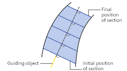
Moving the section by Parallel to itself method
The following can be specified as a guiding object:
•straight-line object — the plane of the section is perpendicular to the line containing the object,
•flat object — the section plane is perpendicular to the object's normal.
The name of the selected object is displayed in the Guiding Object field on the Parameter Panel.
If you need to define a direction using a vector, press the Construct Vector  button to the right of the Guiding Object field. This will start the process of vector construction. Follow the plotting process and press the Create Object button. The system will return to the surface plotting process, the created vector will be automatically selected as the guiding object.
To select this method, click the On the line  button in the Section Movement button group.
With the method of moving the section Along the line, the position of the section plane is defined by a guiding line. At the starting position of the section, its plane is perpendicular to the guiding line. When the section moves, the plane rotates so that it remains perpendicular to this line.
|
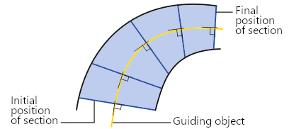
Moving the section using the Along the line
The following can be specified as the guiding line:
•3D curve, consisting of a single contour (including a broken line or its segment, curve having subordinate objects – curves,
•sketch line,
•edge,
•chain of the above objects in any combination.
Names of the indicated object(s) are displayed in the Guiding line field.