|
Dimension Tolerance |
Scroll |
To assign tolerance to a dimension, use elements from the main section of the Parameter Toolbar. In addition, you can assign tolerance to dimension when you configuring dimension text. In this case, click the Assign/change tolerance...  buttonon additional Parameter Panel. It will display a dialog with the same tolerance assignment elements as on the Parameter Toolbar.
Tolerance assignment elements
Item |
Description |
|
Tolerance |
The toggle switch controls whether a dimension has a tolerance. If the toggle switch is in the I position (enabled), the dimension can have a tolerance. Tolerance assignment elements are available. If the toggle switch is in the 0 position (disabled), the dimension has no tolerance. If the toggle switch is moved to this position, the following actions are performed: •tolerance (tolerance class and deviations/limits) assigned to the dimension is removed, •tolerance assignment elements are hidden on the Parameter Toolbar or become unavailable in the dialog, •the Nominal (framed) option is disabled and hidden (becomes unavailable). |
|
Tolerance class |
This field displays the tolerance class specified for the dimension. It’s included when setting all dimensions, except angular dimensions. The icon If the field has a red marquee and an icon |
|
|
Reference |
This button can be used to select the desired tolerance class. Opens the Tolerance classdialog. It is located to the right of the Tolerance Class field. If angular dimensions are set, this button is not displayed. |
|
Show in caption |
This button controls whether the selected tolerance class is displayed in the dimension text. It is located to the right of the Tolerance Class field. If angular dimensions are set, this button is not displayed. |
Deviations/Limits |
This toggle switch can be used to select which tolerance parameters you want to set: maximum dimension deviations or its limit values. To specify maximum deviations, set the Deviations/Limits toggle switch to the Deviations position; to specify limit values, move it to Limits. |
|
Upper/lower deviation, Upper/lower limit |
This field specifies maximum dimension deviations or it's limit values. Displayed fields depend on the position of the Deviations/Limits toggle switch. For angular dimensions, you can only enter deviations and limits manually. For linear, radial and diameter dimensions, deviations and limits can be set manually or obtained automatically if a tolerance class is selected for the dimension. If deviations/limits are entered manually, tolerance class selected is canceled (Tolerance Class field becomes empty). |
|
|
Make deviations equal |
This button can be used to make maximum deviations equal in modulus and opposite in sign. It’s available when deviations are set. When you click this button, the upper deviation is assigned the "+" sign while the lower deviation is assigned "-"; the value of one of the deviations is transferred to the other: •if the cursor is placed in one of the deviation fields, the value of this field will be transferred, •if the cursor is not placed in either field, the value of the upper deviation will be transferred. |
|
Show in caption |
This button controls whether maximum dimension deviations and limits are displayed in the dimension text. |
This option can be used to put the dimension value in a rectangular marquee. It is available if the Tolerance toggle switch is in the I (enabled) position. Once this option is enabled, display of tolerance class and deviations/limits is disabled. If required, you can re-enable display of these values to be included into the marquee. |
||
Dimension limits on one line |
This option can be used to display the dimension limits one by one separated by a hyphen, as opposed to one below another. You can use this option only on the Parameter Toolbar. This option is available if the Tolerance toggle switch is in the I (enabled) position and the Deviations/Limits toggle switch reads Limits. |


Notes on Configuring Tolerance Parameters
•If display in the dimension text is enabled for limits and is disabled for tolerance classes, the nominal value is not displayed in dimension text.
•If insertion into the dimension text is disabled for the selected tolerance class, it is not displayed in the dimension text regardless of the state of the Show in caption button ( or
or  ). The start number for not entering degree of accuracy into dimension caption is set when configuring the current document (see Section Precisions).
•If the dimension contains variables of maximum deviations and the Expression cell in Variables toolbar is populated for at least one of them, tolerance assignment elements located on the Parameter Panel are unavailable.
To select a tolerance class, follow these steps.
1.Click the Directory  button, located to the right of the Tolerance class field. This option opens the Tolerance classdialog.
Dialog contains the tolerance classes table and the elements to select the required class.
Table cells differ in color and font.
The cells with general-purpose tolerance classes are displayed in darker colors with values in bolder fonts (see Figure). The darkest color is used for the cells with preferred tolerance classes.
|
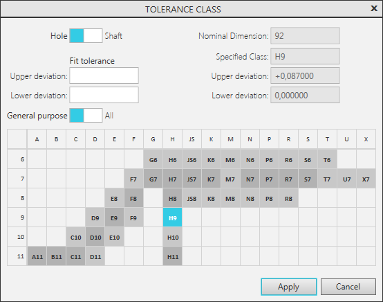
General-purpose tolerance classes,
darker cells correspond to the preferred classes.
The cells with other classes are displayed in light gray with values in standard font. The lightest cells contain values obtained through calculation, the darker cells contain table values.
2.Use the Hole/Shaft toggle switch to select the system where tolerance is to be assigned – hole system or shaft system. A set of tolerance classes in the table matches the selected system.
3.If required, limit the number of displayed classes using one of the following methods.
•To display only classes corresponding to a specific range of deviation values, enter these values into the Upper Deviation and Lower Deviation fields of the Fit Tolerance group.
•To display only general-purpose classes, set the General Purpose/All toggle switch to the General Purpose position.
4.Specify the required tolerance class in the table.
Designation of the selected class and corresponding maximum deviations will be displayed in reference fields of the dialog.
5.To finish class selection, click Apply.
The dialog will close. Designation of the selected class will appear in the Tolerance Class field, and corresponding values will be displayed in deviation/limit fields.