|
Smooth edges display |
Scroll |
For a quick-look analysis of smoothness in the joints between faces of solids or surfaces, you can set a style and color of the smooth edges that is different from the other edges. This display of smooth edges allows for visual check of the presence of smooth joints in the examined areas of the model.
A smooth edge is considered to be a common curve of adjacent faces that are tangent to each other, provided that the specified criterion is satisfied. Such a criterion is the angular tolerance between the tangent faces at the points of the curve; it is defined by the user during the setup. An edge is considered as smooth if the specified angular tolerance is not exceeded. The angle tolerance can vary from 0 to 5 degrees. The greater the value of the angular tolerance, the more smooth edges can be defined in the model, see the figure below (smooth edges are displayed in red).
When working with large assemblies, to save resources, it is recommended to display smooth edges with the same color and style as the regular edges.
Setting up smooth edge parameters is performed in the Smooth edges dialog. In it, you can also disable the display of such edges.
|
|
|
a) |
b) |
c) |
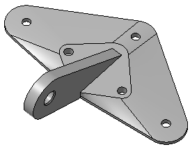
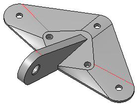
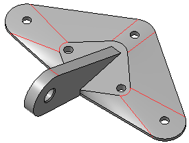
Model with different settings of smooth edges
a) display smooth edges is off, an angle of 0.2° is set,
b) display smooth edges is enabled, angle of 0.2° is set,
c) display smooth edges is enabled, angle of 5° is set.
For more accurate analysis of the smoothness of joints, it is recommended to use the command Check smoothness.