|
Additional features when building a groove |
Scroll |
Building centerlines
By default, a groove is constructed without centerlines.
In order for the created object to have centerlines, enable the With Axes option on the Parameter Panel.
Centerlines are a systemic macro-element: for a straight groove – a linear grid of centers, for an arc – a round grid of centers. The center grid is not connected with the groove and is not rebuilt during its further editing (changing parameters or position).
|
|
a) |
b) |
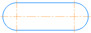
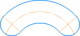
Groove with centerlines: a) straight, b) arched
|
While working in parametric mode A grid of centers is created associated with a groove. |

If the groove is constructed with axes, then the creation of a controlling dimension from its bounding point presents certain complexity. The point is that by default in this case the dimension is not associated with the contour of the groove, which is why it cannot be associative. To set a dimension to the contour, you can use local snap or temporarily disable the coincidence of defining points of the contour and the centerline while setting the dimension. Details...
Setting dimensions
Dimensions can be automatically created for the groove. To that end, enable the With Dimensions option on the Parameters Panel.
When creating a straight groove, the system will auto-set the following dimensions:
•When constructing a groove using the method By centers or From the midpoint to the centers — the distance between the centers of the arcs (with extension lines from the ends of the segment, which forms the side of the groove) and the width of the groove (see figure a),
•When constructing a groove by the method By size or From the midpoint along the dimensions — the length and width of the groove (see Fig. b).
|
|
a) |
b) |
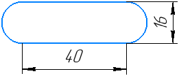
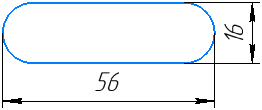
Set the dimensions of the straight groove constructed using various methods:
a) By centers or From the midpoint to the centers,
b) By size or From the midpoint along the dimensions
When creating an arc groove, the following dimensions will be automatically set: the opening angle, the radius of the arc axis, and the groove width.
|
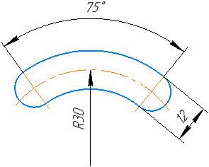
Arc Groove Dimensions
|
While working in parametric mode Dimensions created together with the groove are controlling, i.e. they allow you to change its parameters. |
Splitting into constituent objects
A groove can be constructed as a single object or as separate elements – arcs or segments and arcs. The build option is determined by the state of the option Explode Object.
•If the option is disabled, the groove is constructed as a single object. This object is selected, moved, or edited as a whole.
•If this option is enabled, the groove is split into separate arcs or straight lines and arcs. This object cannot be selected/moved/edited as a whole — each element is processed separately.
If construction with the destruction of the object is performed in parametric mode, restrictions are imposed on the elements that constitute the groove, allowing them to maintain their relative position.
|
|
a) |
b) |
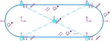
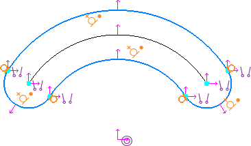
Constraints imposed in parametric mode on objects comprising a groove: a) straight, b) arc-shaped
|
If necessary, a groove, created as a single object, can be destroyed by a command. Explode From the context menu of the Toolbar Panel of the window. In parametric mode, the result of such an explosion (unlike creation with the Explode Object option) is a set of arcs or segments and arcs that are not associated with each other by constraints. |
Line Style Selection
The current line style is displayed in the field of the same name in the Parameter Toolbar. To change the style, expand the list Style and select the desired line. More about selecting line style...
Remembering parameters
When sequentially building objects that have a number of identical parameters, the values of these parameters can be remembered until the command is completed. To do this, specify the parameter values common for the objects, click the button  Remember Status, then continue with the building. More information about remembering parameters...
Example. Construction of several straight grooves with the same length, width and angle.
1.Run the Groove command.
2.Select the construction method by clicking the relevant button in the Method group on the Parameter Toolbar.
3.Set the length, width, and angle of inclination of the groove in the respective fields on the Parameter Panel.
4.Click Remember Status button.
5.Sequentially indicate the center of the arc/midpoint of the arc/groove center (depending on the selected method) and construct the required number of objects.