|
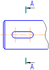
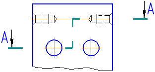
Cut/Section Line |
Scroll |
In KOMPAS-3D you can create:
For precise positioning of the cursor, you can use Snaps and geometrical calculator.
Immediately after the section line is created, it starts automatically command to create a new view. Once running this command has been complete, a new view in the drawing whose designation is associatively linked to the cut/section line will appear.
|
You can give up creation of a new view by pressing the Interrupt commandbutton. However, it is not recommended to do that since manual creation of a view and generation of a link between its designation and the cut/section line will take extra time. Besides, placement of the view along the arrow in a separate view allows for rapidly changing the scale of image and makes the detailing of drawing more convenient. |

When building a cut line, a automatically create hyperlink, linking the designation to the newly created view.
To create a cut or section line, use the Cut/Section Line  command.

Step-by-step instructions
1.Set the initial and final points of the line of cut.
After indication of these points, a designation phantom will appear in the graphic area.
If necessary, you can set the direction of the line of cut. To that end, before indication of the final point select a straight-line object.
On aiming the cursor at the object, the object will be highlighted, and the cursor will take the shape of square "trap".
After the indication of the guiding object, its name will appear in the Object field on the Parameter Panel. Depending on the direction of movement of the cursor on indication of the final point, the line of a cut will be parallel or perpendicular to the selected object.
2.Automatically generated caption text is displayed in the Text field and on the phantom of the line of cut. If necessary, change the caption and/or its typeface. Generation of the designation text of the line of cut is similar to Generation of the designation text for a direction arrow.
3.Indicate, near which of the arrows the additional text, if any, should be placed. To that end, press the required button in the Additional text group:
 At First Arrow,
 At Second Arrow.
If the additional text is not used, the status of buttons of this group does not matter.
4.Select the type of arrow using the Arrow dropdown list.
|
The list of arrows available for selection, as well as the sequence of arrows in the list is determined by the setting of the filter done in the Symbols for mechanical engineering – Cut/section Line – Arrow filter section in the dialog for setting up the current document. |
5.Click that side of the cut/section line where arrows should be placed.
After setting the position of arrows, building the line of cut ends automatically.
|
Cut Line
To create a complex cut or section line, use the Complex Cut/Section Line  .
.
Step-by-step instructions
1.Indicate the vertices of the line of cut.
If necessary, you can set the direction of segments of the line of cut. To that end, prior to indication of the final point of segment select a straight-line object. On aiming the cursor at the object, the object will be highlighted, and the cursor will take the shape of square "trap".
After indication of the object, its name will appear in the Object field on the Parameter Panel. Depending on the direction of the cursor movement, the indication of the final point the segment of the line of cut will be placed in parallel or perpendicularly to the selected object.
After indication of the final point of segment, the Object field will be cleared.
To create a section line with segments perpendicular to each other (for example, when designing a stepped section), enable the mode orthogonal drawing.
2.If it is required to edit the line of cut, switch to the edit mode. In this mode, you can change the position of vertices, delete vertices, create kinks on built segments.
To continue building a line of cut, return to the Creation mode.
3.Automatically generated caption text is displayed in the Text field and on the designation phantom. If necessary, change the caption and/or its typeface. That is possible only in the Edit mode.
Generation of the designation text of the line of cut is similar to Generation of the designation text of the direction arrow.
4.Indicate, near which of the arrows the additional text, if any, should be placed. To that end, press the required button in the Additional text group:
At First Arrow,
At Second Arrow.
If the additional text is not used, the status of buttons of this group does not matter.
5.Select the type of arrow using the Arrow dropdown list.
|
The list of arrows available for selection, as well as the sequence of arrows in the list is determined by the setting of the filter done in the Symbols for mechanical engineering – Cut/section Line – Arrow filter section in the dialog for setting up the current document. |
6.Indicate, on which side of the line of cut the arrows should be placed. For this, use the Change Direction button to the right of the element Arrow Direction  .
.
7.To complete building a line of cut, press the Create object  .
.
|
Complex Cut Line